This thread has been locked.

If you have a related question, please click the "Ask a related question" button in the top right corner. The newly created question will be automatically linked to this question.

CCS/TMS320F28075: PWM for ZVS FB

Part Number: TMS320F28075
Other Parts Discussed in Thread: C2000WARE

Tool/software: Code Composer Studio

Hi,

I am working on TMS320f28075 32 bit microcontroller for ZVS full bridge application.

I used two sets of PWMs (PWM2A, PWM2B and PWM6A, PWM6B )for generating phase shifted PWM. PWM2B and 6B are complimentary signals of PWM2A and 6A respectively. PWM2A and 6A corresponds to top switches and PWM2B and 6B for bottom switches.The Pulse width was set for 50% duty cycle using CMP registers. TBPHS register was used to phase shift the PWMs. I find that when the PWM is turned ON, the first pulse observed is less than 50% duty and is different for PWM2A and PWM6A.(see figure below).I tried turning on various times and each instance showed different behaviour. Note that this behaviour is observed only in first cycle of PWM.  Could anyone tell me what could have gone wrong? Following is the configuration used for PWM module:

EPwm2Regs.TBPRD = 1200;
EPwm2Regs.TBCTL.bit.CTRMODE = TB_COUNT_UPDOWN;
EPwm2Regs.TBCTL.bit.PRDLD = TB_SHADOW;
EPwm2Regs.TBCTL.bit.HSPCLKDIV = TB_DIV1; //High Speed Time Base Clock Pre-Scale Bits,TBCLK = EPWMCLK / (HSPCLKDIV x CLKDIV)., PWM period = 2 × TBPRD × TBCLK
EPwm2Regs.TBCTL.bit.CLKDIV = TB_DIV1;
EPwm2Regs.TBCTL.bit.FREE_SOFT = 2u;

EPwm2Regs.TBCTL.bit.PHSEN = TB_DISABLE;
EPwm2Regs.TBCTL.bit.SYNCOSEL = TB_CTR_ZERO;

EPwm2Regs.CMPA.bit.CMPA = 300; 
EPwm2Regs.CMPB.bit.CMPB = 300;

EPwm2Regs.AQCTLA.bit.CAU = AQ_SET;
EPwm2Regs.AQCTLA.bit.CBU = AQ_NO_ACTION;
EPwm2Regs.AQCTLA.bit.CBD = AQ_NO_ACTION;
EPwm2Regs.AQCTLA.bit.CAD = AQ_CLEAR;
EPwm2Regs.CMPCTL.bit.SHDWAMODE = CC_SHADOW;
EPwm2Regs.CMPCTL.bit.LOADASYNC=CC_CTR_ZERO; 
EPwm2Regs.CMPCTL.bit.LOADAMODE=CC_CTR_ZERO;

EPwm2Regs.AQCTLB.bit.CAU = AQ_CLEAR;
EPwm2Regs.AQCTLB.bit.CBU = AQ_NO_ACTION;
EPwm2Regs.AQCTLB.bit.CBD = AQ_NO_ACTION;
EPwm2Regs.AQCTLB.bit.CAD = AQ_SET;
EPwm2Regs.CMPCTL.bit.SHDWAMODE = CC_SHADOW;
EPwm2Regs.CMPCTL.bit.LOADASYNC=CC_CTR_ZERO; 
EPwm2Regs.CMPCTL.bit.LOADAMODE=CC_CTR_ZERO; 

EPwm6Regs.TBPRD = PWM_TBPRD;
EPwm6Regs.TBCTL.bit.CTRMODE = TB_COUNT_UPDOWN;
EPwm6Regs.TBCTL.bit.PRDLD = TB_SHADOW;
EPwm6Regs.TBCTL.bit.HSPCLKDIV = TB_DIV1; //High Speed Time Base Clock Pre-Scale Bits,TBCLK = EPWMCLK / (HSPCLKDIV x CLKDIV)., PWM period = 2 × TBPRD × TBCLK
EPwm6Regs.TBCTL.bit.CLKDIV = TB_DIV1;
EPwm6Regs.TBCTL.bit.FREE_SOFT = 2u;

EPwm6Regs.TBCTL.bit.PHSEN = TB_ENABLE;
EPwm6Regs.TBCTL.bit.SYNCOSEL = TB_SYNC_IN;

EPwm6Regs.CMPA.bit.CMPA = 300;
EPwm6Regs.CMPB.bit.CMPB = 300;

EPwm6Regs.AQCTLA.bit.CAD = AQ_CLEAR;
EPwm6Regs.AQCTLA.bit.CBD = AQ_NO_ACTION;
EPwm6Regs.AQCTLA.bit.CBU = AQ_NO_ACTION;
EPwm6Regs.AQCTLA.bit.CAU = AQ_SET;
EPwm6Regs.CMPCTL.bit.SHDWAMODE = CC_SHADOW;
EPwm6Regs.CMPCTL.bit.LOADASYNC=CC_CTR_ZERO; 
EPwm6Regs.CMPCTL.bit.LOADAMODE=CC_CTR_PRD; 
/* For OUtput B */
// Action Qualifier SubModule Registers
EPwm6Regs.AQCTLB.bit.CAU = AQ_CLEAR;
EPwm6Regs.AQCTLB.bit.CBU = AQ_NO_ACTION;
EPwm6Regs.AQCTLB.bit.CBD = AQ_NO_ACTION;
EPwm6Regs.AQCTLB.bit.CAD =AQ_SET;
EPwm6Regs.CMPCTL.bit.SHDWAMODE = CC_SHADOW;
EPwm6Regs.CMPCTL.bit.LOADASYNC=CC_CTR_ZERO; 
EPwm6Regs.CMPCTL.bit.LOADAMODE=CC_CTR_PRD; 

I am updating the TBPHS register of PWM 6 in CLA interrupt.

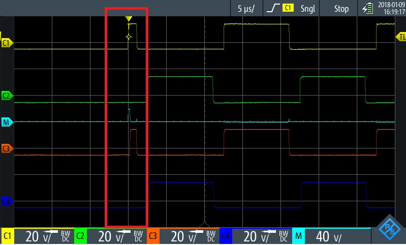
Figure: M is the difference between C1 and C3.

Thanks in advance!

Regards,

Anjana

  • Hi Anjana,

    Are you wrapping your ePWM configurations in

    EALLOW;
    CpuSysRegs.PCLKCR0.bit.TBCLKSYNC =0;
    EDIS;

    //<ePWM configurations>

    EALLOW;
    CpuSysRegs.PCLKCR0.bit.TBCLKSYNC =1;
    EDIS;

    This will ensure that the ePWM is not running while it is being configured and will also ensure that all ePWMs start together.
  • Hi Devin,

    Thanks for your reply.
    Yes,I have done that.Following is the sequence that I adopted to call the PWMs.

    PWM_OFF(); // Here I set TBCLKSYNC=0;
    PWM2_Config(); //Configuring PWM2
    PWM6_Config(); //Configuring PWM6
    PWM_ON(); //Here I set TBCLKSYNC=1;

    After a delay of 10ms,
    PWM_init(); //Enable clock for PWM modules

    Another point which I observed was that,if GPIO pin for PWM2 is muxed first, PWM2 will start before PWM6 and vice versa.

    So is that initial delay expected?

    Regards,
    Anjana
  • Hi Anjana,

    Usually I think TBCLKSYNC=1 would be the last step in process and would be written immediately when you want the ePWM to start.  I think you want your GPIO muxes to be setup before you trigger this last step.

    For example, in the c2000ware epwm_up_aq_cpu01.c example, the order is:

    • Enable ePWM clocks
      • e.g. CpuSysRegs.PCLKCR2.bit.EPWM1=1;
    • Setup ePWM GPIO
      • e.g. InitEPwm1Gpio();
    • Map ePWM ISRs
    • CpuSysRegs.PCLKCR0.bit.TBCLKSYNC = 0;
    • ePWM peripheral config
      • e.g.     InitEPwm1Example();
    • CpuSysRegs.PCLKCR0.bit.TBCLKSYNC = 1;
    • Enable ISR flags and global ISR enable

  • Hi Devin,

    Sorry for delayed response.

    I tried the order you mentioned above for starting the ePWM. Now there is a delay of 300ns between PWM2 and PWM6. The pulse width is more or less the same for both.
    Is there any limitation for using the dead band module if we use the phase shift register.?

    Thanks,
    Anjana
  • Hi Anjana,

    This seems like more of an initialization issue than a restriction with the module. Can you toggle a GPIO after you set TBCLKSYNC=1 and send us a waveform showing the PWMs?

    How are you routing EPWM2's syncout to EPWM6's syncin to trigger the phase load? See the figure "Time-Base Counter Synchronization Scheme" in the TRM for your device.

    Regards,
    Kris

  • Hi Anjana,

    Since we have not heard back from you, we hope your issue is resolved and we are going to begin the process to close this thread. If your issue is ongoing you can stop the process and post your response.

    Thank you for choosing TI.

    Regards,
    Kris
  • Hi Kris,
    Apologies for late reply.

    The above mentioned issue was resolved partially.

    I have used PWM 1 as Master and PWM2 and PWM6 as slaves and have configured as shown below.

    EPwm1Regs.TBCTL.bit.PHSEN = TB_DISABLE;
    EPwm1Regs.TBCTL.bit.SYNCOSEL = TB_CTR_ZERO;

    EPwm2Regs.TBCTL.bit.PHSEN = TB_ENABLE;
    EPwm2Regs.TBCTL.bit.SYNCOSEL = TB_SYNC_IN;

    EPwm6Regs.TBCTL.bit.PHSEN = TB_ENABLE;
    EPwm6Regs.TBCTL.bit.SYNCOSEL = TB_SYNC_IN;

    When I check the PWM outputs, while running the hardware in closed loop mode,there are situations when one Pulse is missing .

    Is the above configuration details what you were looking for?

    Thanks,
    Anjana
  • Hi Anjana,

    Not quite. I'm looking for how you are programming the SYNCSELECT register. You can find details on page 1994 here:

    www.ti.com/.../spruhm8g.pdf

    This will determine how the sync outs are routed between EPWM modules. You can reference Figure 16-8 Time-Base Counter Synchronization Scheme on page 2036 for a visual of the connections.

    Regards,
    Kris
  • Hi Kris,

    I have not used the SYNCSELECT register. I went through the details you had mentioned above but have a doubt there.
    EPWM1 and EPWM2 lies in the same sync chain but for EPWM6,should I use the EPWM4SYNCOUT for routing as EPWM4 and 6 as they lie in the same chain?
    From the reference manual of the controller ,what I understood is to use EPwmxRegs.TBCTL.bit.SYNCOSEL = TB_SYNC_IN; for slave configuration.Do I need to configure SYNCSELECT addition to SYNCOSEL ?

    Regards,
    Anjana
  • Hi Anjana,

    The SYNCOSEL register configures the sync out signal for a specific EPWM module. The SYNCSELECT register (in combination with the figure I referenced) contols where that SYNCO signal from that EPWM is routed, and therefore, controls what each module sees at its sync in connection.

    For EPWM1 and EPWM2 it shouldn't be making a difference as you said. For EPWM6, you could use SYNCSELECT to configure EPWM1's SYNCO to go to the EPWM4 chain. If you have not configured EPWM4 and 5 then I believe the default is the sync will just pass through (but you may need to experiment with this a bit). If EPWM3 is available and you want to keep it simple, you could migrate the EPWM6 code to EPWM3. Any of these options should work fine.

    To answer your question, you would use EPWM4SYNCOUT for EPWM6's SYNCI since it is in the EPWM4 chain.

    Regards,
    Kris
  • Hi Kris,

    Thanks a lot! I was really confused with the configuration of PWM modules. Let me check if PWM3 is available else will try the EPWM4SYNCOUT option.

    Regards,
    Anjana