Hi, Champs,
One of my customer is using usb_dev_serial example code to implement USB communication but there's a problem.
They simply modified some configurations in the example file as attached with below items:
1. Comment UART configuration and while() content;
2. Add 1ms timer interrupt to send 168bytes;
3. Add RxLengthFromHost for indicating message received.
Customer targets to received command from host every 1ms, and then reply 168bytes contents 60000 times.
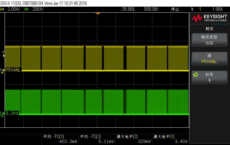
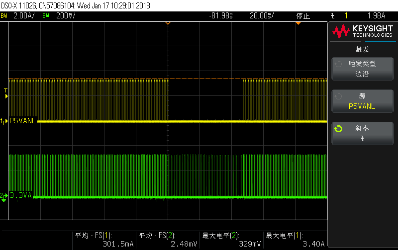
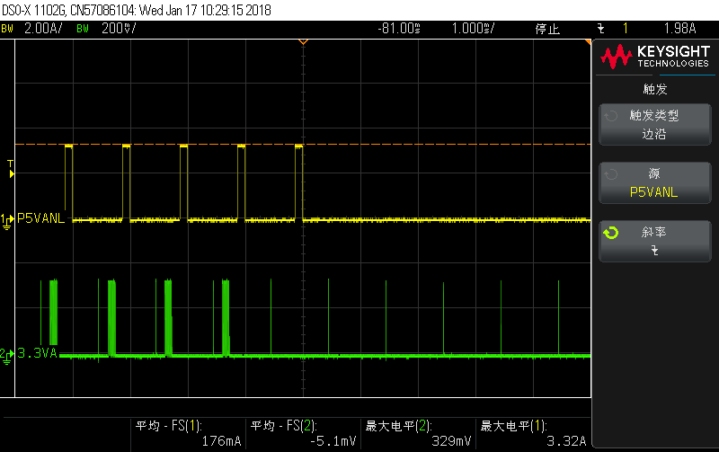
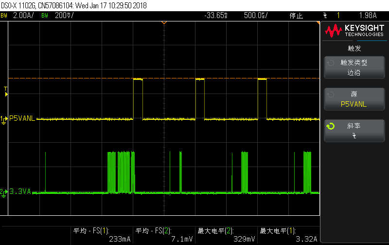
They use host program to receive the reply and calculate if it's communicated correctly, while the problem is, they always get missed message, which is every 500ms, there will be 40~50ms without data transmitted, and by further confirmation, it seems to be F28377D doesn't send even if Tx is enabled after FIFO is written to.
Could anyone please help to check the code and advise if we missed anything, or point out where the problem is?
//###########################################################################
//
// FILE: usb_dev_serial.c
//
// TITLE: Main routines for the USB CDC serial example.
//
//###########################################################################
// $TI Release: F2837xD Support Library v3.03.00.00 $
// $Release Date: Thu Dec 7 18:51:32 CST 2017 $
// $Copyright:
// Copyright (C) 2013-2017 Texas Instruments Incorporated - http://www.ti.com/
//
// Redistribution and use in source and binary forms, with or without
// modification, are permitted provided that the following conditions
// are met:
//
// Redistributions of source code must retain the above copyright
// notice, this list of conditions and the following disclaimer.
//
// Redistributions in binary form must reproduce the above copyright
// notice, this list of conditions and the following disclaimer in the
// documentation and/or other materials provided with the
// distribution.
//
// Neither the name of Texas Instruments Incorporated nor the names of
// its contributors may be used to endorse or promote products derived
// from this software without specific prior written permission.
//
// THIS SOFTWARE IS PROVIDED BY THE COPYRIGHT HOLDERS AND CONTRIBUTORS
// "AS IS" AND ANY EXPRESS OR IMPLIED WARRANTIES, INCLUDING, BUT NOT
// LIMITED TO, THE IMPLIED WARRANTIES OF MERCHANTABILITY AND FITNESS FOR
// A PARTICULAR PURPOSE ARE DISCLAIMED. IN NO EVENT SHALL THE COPYRIGHT
// OWNER OR CONTRIBUTORS BE LIABLE FOR ANY DIRECT, INDIRECT, INCIDENTAL,
// SPECIAL, EXEMPLARY, OR CONSEQUENTIAL DAMAGES (INCLUDING, BUT NOT
// LIMITED TO, PROCUREMENT OF SUBSTITUTE GOODS OR SERVICES; LOSS OF USE,
// DATA, OR PROFITS; OR BUSINESS INTERRUPTION) HOWEVER CAUSED AND ON ANY
// THEORY OF LIABILITY, WHETHER IN CONTRACT, STRICT LIABILITY, OR TORT
// (INCLUDING NEGLIGENCE OR OTHERWISE) ARISING IN ANY WAY OUT OF THE USE
// OF THIS SOFTWARE, EVEN IF ADVISED OF THE POSSIBILITY OF SUCH DAMAGE.
// $
//###########################################################################
//
// Included Files
//
#include "F28x_Project.h"
#include <stdbool.h>
#include <stdint.h>
#include "inc/hw_ints.h"
#include "inc/hw_memmap.h"
#include "inc/hw_types.h"
#include "inc/hw_uart.h"
#include "driverlib/debug.h"
#include "driverlib/interrupt.h"
#include "driverlib/sysctl.h"
#include "driverlib/systick.h"
#include "driverlib/uart.h"
#include "driverlib/usb.h"
#include "driverlib/usb_hal.h"
#include "driverlib/rom.h"
#include "include/usblib.h"
#include "include/usbcdc.h"
#include "include/usb_ids.h"
#include "include/device/usbdevice.h"
#include "include/device/usbdcdc.h"
#include "utils/ustdlib.h"
#include "usb_serial_structs.h"
//*****************************************************************************
//
//! \addtogroup cpu01_example_list
//! <h1>USB Serial Device (usb_dev_serial)</h1>
//!
//! This example application turns the evaluation kit into a virtual serial
//! port when connected to the USB host system. The application supports the
//! USB Communication Device Class, Abstract Control Model to redirect UART0
//! traffic to and from the USB host system.
//!
//! Connect USB cables from your PC to both the mini and microUSB connectors on
//! the controlCARD.Figure out what COM ports your controlCARD is enumerating
//! (typically done using Device Manager in Windows) and open a serial terminal
//! to each of with the settings 115200 Baud 8-N-1. Characters typed in one
//! terminal should be echoed in the other and vice versa.
//!
//! A driver information (INF) file for use with Windows XP and
//! Windows 7 can be found in the windows_drivers directory.
//
//*****************************************************************************
//*****************************************************************************
//
// Configuration and tuning parameters.
//
//*****************************************************************************
//*****************************************************************************
//
// The system tick rate expressed both as ticks per second and a millisecond
// period.
//
//*****************************************************************************
#define SYSTICKS_PER_SECOND 100
#define SYSTICK_PERIOD_MS (1000 / SYSTICKS_PER_SECOND)
//*****************************************************************************
//
// Variables tracking transmit and receive counts.
//
//*****************************************************************************
volatile uint32_t g_ui32UARTTxCount = 0;
volatile uint32_t g_ui32UARTRxCount = 0;
#ifdef DEBUG
uint32_t g_ui32UARTRxErrors = 0;
#endif
//*****************************************************************************
//
// The base address, peripheral ID and interrupt ID of the UART that is to
// be redirected.
//
//*****************************************************************************
//*****************************************************************************
//
// Defines required to redirect UART0 via USB.
//
//*****************************************************************************
#define USB_UART_BASE UARTA_BASE
#define USB_UART_PERIPH SYSCTL_PERIPH_SCI1
#define USB_UART_INT INT_SCIRXINTA
//*****************************************************************************
//
// Default line coding settings for the redirected UART.
//
//*****************************************************************************
#define DEFAULT_BIT_RATE 115200
#define DEFAULT_UART_CONFIG (UART_CONFIG_WLEN_8 | UART_CONFIG_PAR_NONE | \
UART_CONFIG_STOP_ONE)
//*****************************************************************************
//
// GPIO peripherals and pins muxed with the redirected UART. These will depend
// upon the IC in use and the UART selected in USB_UART_BASE. Be careful that
// these settings all agree with the hardware you are using.
//
//*****************************************************************************
//*****************************************************************************
//
// Defines required to redirect UART0 via USB.
//
//*****************************************************************************
//#define TX_GPIO_BASE GPIO_PORTA_BASE
//#define TX_GPIO_PERIPH SYSCTL_PERIPH_GPIOA
//#define TX_GPIO_PIN GPIO_PIN_1
//
//#define RX_GPIO_BASE GPIO_PORTA_BASE
//#define RX_GPIO_PERIPH SYSCTL_PERIPH_GPIOA
//#define RX_GPIO_PIN GPIO_PIN_0
//*****************************************************************************
//
// Flag indicating whether or not we are currently sending a Break condition.
//
//*****************************************************************************
static bool g_bSendingBreak = false;
//*****************************************************************************
//
// Global system tick counter
//
//*****************************************************************************
volatile uint32_t g_ui32SysTickCount = 0;
//*****************************************************************************
//
// Flags used to pass commands from interrupt context to the main loop.
//
//*****************************************************************************
#define COMMAND_PACKET_RECEIVED 0x00000001
#define COMMAND_STATUS_UPDATE 0x00000002
volatile uint32_t g_ui32Flags = 0;
char *g_pcStatus;
//*****************************************************************************
//
// Global flag indicating that a USB configuration has been set.
//
//*****************************************************************************
static volatile bool g_bUSBConfigured = false;
//ADD
uint32_t RxLengthFromHost = 0;
uint32_t USBBuffSpace = 0;
uint8_t USBRxBuf[256];
uint8_t USBTxBuf[256];
uint8_t UsbTxTest = 0;
uint32_t UsbTxTest2 = 0;
#define USB_RX_LENGTH 255
__interrupt void cpu_timer0_isr(void);
//*****************************************************************************
//
// Internal function prototypes.
//
//*****************************************************************************
static void USBUARTPrimeTransmit(uint32_t ui32Base);
static void CheckForSerialStateChange(const tUSBDCDCDevice *psDevice,
int32_t i32Errors);
static void SetControlLineState(uint16_t ui16State);
static bool SetLineCoding(tLineCoding *psLineCoding);
static void GetLineCoding(tLineCoding *psLineCoding);
static void SendBreak(bool bSend);
//*****************************************************************************
//
// The error routine that is called if the driver library encounters an error.
//
//*****************************************************************************
#ifdef DEBUG
void
__error__(char *pcFilename, uint32_t ui32Line)
{
while(1)
{
}
}
#endif
//*****************************************************************************
//
// This function is called whenever serial data is received from the UART.
// It is passed the accumulated error flags from each character received in
// this interrupt and determines from them whether or not an interrupt
// notification to the host is required.
//
// If a notification is required and the control interrupt endpoint is idle,
// we send the notification immediately. If the endpoint is not idle, we
// accumulate the errors in a global variable which will be checked on
// completion of the previous notification and used to send a second one
// if necessary.
//
//*****************************************************************************
static void
CheckForSerialStateChange(const tUSBDCDCDevice *psDevice, int32_t i32Errors)
{
uint16_t ui16SerialState;
//
// Clear our USB serial state. Since we are faking the handshakes, always
// set the TXCARRIER (DSR) and RXCARRIER (DCD) bits.
//
ui16SerialState = USB_CDC_SERIAL_STATE_TXCARRIER |
USB_CDC_SERIAL_STATE_RXCARRIER;
//
// Are any error bits set?
//
if(i32Errors)
{
//
// At least one error is being notified so translate from our hardware
// error bits into the correct state markers for the USB notification.
//
if(i32Errors & UART_RXST_OE)
{
ui16SerialState |= USB_CDC_SERIAL_STATE_OVERRUN;
}
if(i32Errors & UART_RXST_PE)
{
ui16SerialState |= USB_CDC_SERIAL_STATE_PARITY;
}
if(i32Errors & UART_RXST_FE)
{
ui16SerialState |= USB_CDC_SERIAL_STATE_FRAMING;
}
if(i32Errors & UART_RXST_BRKDT)
{
ui16SerialState |= USB_CDC_SERIAL_STATE_BREAK;
}
// Call the CDC driver to notify the state change.
USBDCDCSerialStateChange((void *)psDevice, ui16SerialState);
}
}
//*****************************************************************************
//
// Read as many characters from the UART FIFO as we can and move them into
// the CDC transmit buffer.
//
// \return Returns UART error flags read during data reception.
//
//*****************************************************************************
static int32_t
ReadUARTData(void)
{
int32_t i32Char, i32Errors;
uint8_t ui8Char;
uint32_t ui32Space;
//
// Clear our error indicator.
//
i32Errors = 0;
//
// How much space do we have in the buffer?
//
ui32Space = USBBufferSpaceAvailable((tUSBBuffer *)&g_sTxBuffer);
//
// Read data from the UART FIFO until there is none left or we run
// out of space in our receive buffer.
//
while(ui32Space && UARTCharsAvail(USB_UART_BASE))
{
//
// Read a character from the UART FIFO into the ring buffer if no
// errors are reported.
//
i32Char = UARTCharGetNonBlocking(USB_UART_BASE);
//
// If the character did not contain any error notifications,
// copy it to the output buffer.
//
if(!(i32Char & ~0xFF))
{
ui8Char = (uint8_t)(i32Char & 0xFF);
USBBufferWrite((tUSBBuffer *)&g_sTxBuffer,
(uint8_t *)&ui8Char, 1);
//
// Decrement the number of bytes we know the buffer can accept.
//
ui32Space--;
}
else
{
#ifdef DEBUG
//
// Increment our receive error counter.
//
g_ui32UARTRxErrors++;
#endif
//
// Update our error accumulator.
//
i32Errors |= i32Char;
}
//
// Update our count of bytes received via the UART.
//
g_ui32UARTRxCount++;
}
//
// Pass back the accumulated error indicators.
//
return(i32Errors);
}
//*****************************************************************************
//
// Take as many bytes from the transmit buffer as we have space for and move
// them into the USB UART's transmit FIFO.
//
//*****************************************************************************
static void
USBUARTPrimeTransmit(uint32_t ui32Base)
{
uint32_t ui32Read;
uint8_t ui8Char;
//
// If we are currently sending a break condition, don't receive any
// more data. We will resume transmission once the break is turned off.
//
if(g_bSendingBreak)
{
return;
}
//
// If there is space in the UART FIFO, try to read some characters
// from the receive buffer to fill it again.
//
while(UARTSpaceAvail(ui32Base))
{
//
// Get a character from the buffer.
//
ui32Read = USBBufferRead((tUSBBuffer *)&g_sRxBuffer, &ui8Char, 1);
//
// Did we get a character?
//
if(ui32Read)
{
//
// Place the character in the UART transmit FIFO.
//
UARTCharPutNonBlocking(ui32Base, ui8Char);
//
// Update our count of bytes transmitted via the UART.
//
g_ui32UARTTxCount++;
}
else
{
//
// We ran out of characters so exit the function.
//
return;
}
}
}
//*****************************************************************************
//
// Interrupt handler for the system tick counter.
//
//*****************************************************************************
__interrupt void
SysTickIntHandler(void)
{
//
// Update our system time.
//
g_ui32SysTickCount++;
PieCtrlRegs.PIEACK.all |= 1;
}
//*****************************************************************************
//
// Interrupt handler for the UART TX which is being redirected via USB.
//
//*****************************************************************************
__interrupt void
USBUARTTXIntHandler(void)
{
uint32_t ui32Ints;
ui32Ints = UARTIntStatus(USB_UART_BASE, true);
//
// Handle transmit interrupts.
//
if(ui32Ints & UART_INT_TXRDY)
{
//
// Move as many bytes as possible into the transmit FIFO.
//
USBUARTPrimeTransmit(USB_UART_BASE);
//
// If the output buffer is empty, turn off the transmit interrupt.
//
if(!USBBufferDataAvailable(&g_sRxBuffer))
{
UARTIntDisable(USB_UART_BASE, UART_INT_TXRDY);
}
}
PieCtrlRegs.PIEACK.all = 0x100;
}
//*****************************************************************************
//
// Interrupt handler for the UART RX which is being redirected via USB.
//
//*****************************************************************************
__interrupt void
USBUARTRXIntHandler(void)
{
uint32_t u3i2Ints;
u3i2Ints = UARTIntStatus(USB_UART_BASE, true);
//
// Handle receive interrupts.
//
if(u3i2Ints & UART_INT_RXRDY_BRKDT)
{
//
// Read the UART's characters into the buffer.
//
ReadUARTData();
}
else if(u3i2Ints & UART_INT_RXERR)
{
//
//Notify Host of our error
//
CheckForSerialStateChange(&g_sCDCDevice, UARTRxErrorGet(USB_UART_BASE));
//
//Clear the error and continue
//
UARTRxErrorClear(USB_UART_BASE);
}
PieCtrlRegs.PIEACK.all = 0x100;
}
//*****************************************************************************
//
// Set the state of the RS232 RTS and DTR signals.
//
//*****************************************************************************
static void
SetControlLineState(uint16_t ui16State)
{
//
// TODO: If configured with GPIOs controlling the handshake lines,
// set them appropriately depending upon the flags passed in the wValue
// field of the request structure passed.
//
}
//*****************************************************************************
//
// Set the communication parameters to use on the UART.
//
//*****************************************************************************
static bool
SetLineCoding(tLineCoding *psLineCoding)
{
uint32_t ui32Config;
bool bRetcode;
//
// Assume everything is OK until we detect any problem.
//
bRetcode = true;
//
// Word length. For invalid values, the default is to set 8 bits per
// character and return an error.
//
switch(psLineCoding->ui8Databits)
{
case 5:
{
ui32Config = UART_CONFIG_WLEN_5;
break;
}
case 6:
{
ui32Config = UART_CONFIG_WLEN_6;
break;
}
case 7:
{
ui32Config = UART_CONFIG_WLEN_7;
break;
}
case 8:
{
ui32Config = UART_CONFIG_WLEN_8;
break;
}
default:
{
ui32Config = UART_CONFIG_WLEN_8;
bRetcode = false;
break;
}
}
//
// Parity. For any invalid values, we set no parity and return an error.
//
switch(psLineCoding->ui8Parity)
{
case USB_CDC_PARITY_NONE:
{
ui32Config |= UART_CONFIG_PAR_NONE;
break;
}
case USB_CDC_PARITY_ODD:
{
ui32Config |= UART_CONFIG_PAR_ODD;
break;
}
case USB_CDC_PARITY_EVEN:
{
ui32Config |= UART_CONFIG_PAR_EVEN;
break;
}
case USB_CDC_PARITY_MARK:
{
ui32Config |= UART_CONFIG_PAR_ONE;
break;
}
case USB_CDC_PARITY_SPACE:
{
ui32Config |= UART_CONFIG_PAR_ZERO;
break;
}
default:
{
ui32Config |= UART_CONFIG_PAR_NONE;
bRetcode = false;
break;
}
}
//
// Stop bits. Our hardware only supports 1 or 2 stop bits whereas CDC
// allows the host to select 1.5 stop bits. If passed 1.5 (or any other
// invalid or unsupported value of ui8Stop, we set up for 1 stop bit but
// return an error in case the caller needs to Stall or otherwise report
// this back to the host.
//
switch(psLineCoding->ui8Stop)
{
//
// One stop bit requested.
//
case USB_CDC_STOP_BITS_1:
{
ui32Config |= UART_CONFIG_STOP_ONE;
break;
}
//
// Two stop bits requested.
//
case USB_CDC_STOP_BITS_2:
{
ui32Config |= UART_CONFIG_STOP_TWO;
break;
}
//
// Other cases are either invalid values of ui8Stop or values that we
// cannot support so set 1 stop bit but return an error.
//
default:
{
ui32Config = UART_CONFIG_STOP_ONE;
bRetcode |= false;
break;
}
}
//
// Set the UART mode appropriately.
//
UARTConfigSetExpClk(USB_UART_BASE, SysCtlLowSpeedClockGet(SYSTEM_CLOCK_SPEED),
readusb32_t(&(psLineCoding->ui32Rate)), ui32Config);
//
// Let the caller know if we had a problem or not.
//
return(bRetcode);
}
//*****************************************************************************
//
// Get the communication parameters in use on the UART.
//
//*****************************************************************************
static void
GetLineCoding(tLineCoding *psLineCoding)
{
uint32_t ui32Config;
uint32_t ui32Rate;
//
// Get the current line coding set in the UART.
//
UARTConfigGetExpClk(USB_UART_BASE, SysCtlLowSpeedClockGet(SYSTEM_CLOCK_SPEED),
&ui32Rate, &ui32Config);
writeusb32_t(&(psLineCoding->ui32Rate), ui32Rate);
//
// Translate the configuration word length field into the format expected
// by the host.
//
switch(ui32Config & UART_CONFIG_WLEN_MASK)
{
case UART_CONFIG_WLEN_8:
{
psLineCoding->ui8Databits = 8;
break;
}
case UART_CONFIG_WLEN_7:
{
psLineCoding->ui8Databits = 7;
break;
}
case UART_CONFIG_WLEN_6:
{
psLineCoding->ui8Databits = 6;
break;
}
case UART_CONFIG_WLEN_5:
{
psLineCoding->ui8Databits = 5;
break;
}
}
//
// Translate the configuration parity field into the format expected
// by the host.
//
switch(ui32Config & UART_CONFIG_PAR_MASK)
{
case UART_CONFIG_PAR_NONE:
{
psLineCoding->ui8Parity = USB_CDC_PARITY_NONE;
break;
}
case UART_CONFIG_PAR_ODD:
{
psLineCoding->ui8Parity = USB_CDC_PARITY_ODD;
break;
}
case UART_CONFIG_PAR_EVEN:
{
psLineCoding->ui8Parity = USB_CDC_PARITY_EVEN;
break;
}
}
//
// Translate the configuration stop bits field into the format expected
// by the host.
//
switch(ui32Config & UART_CONFIG_STOP_MASK)
{
case UART_CONFIG_STOP_ONE:
{
psLineCoding->ui8Stop = USB_CDC_STOP_BITS_1;
break;
}
case UART_CONFIG_STOP_TWO:
{
psLineCoding->ui8Stop = USB_CDC_STOP_BITS_2;
break;
}
}
}
//*****************************************************************************
//
// This function sets or clears a break condition on the redirected UART RX
// line. A break is started when the function is called with \e bSend set to
// \b true and persists until the function is called again with \e bSend set
// to \b false.
//
//*****************************************************************************
static void
SendBreak(bool bSend)
{
//
//C28x SCI cannot send break conditions
//
return;
}
//*****************************************************************************
//
// Handles CDC driver notifications related to control and setup of the device.
//
// \param pvCBData is the client-supplied callback pointer for this channel.
// \param ui32Event identifies the event we are being notified about.
// \param ui32MsgValue is an event-specific value.
// \param pvMsgData is an event-specific pointer.
//
// This function is called by the CDC driver to perform control-related
// operations on behalf of the USB host. These functions include setting
// and querying the serial communication parameters, setting handshake line
// states and sending break conditions.
//
// \return The return value is event-specific.
//
//*****************************************************************************
uint32_t
ControlHandler(void *pvCBData, uint32_t ui32Event,
uint32_t ui32MsgValue, void *pvMsgData)
{
uint32_t ui32IntsOff;
//
// Which event are we being asked to process?
//
switch(ui32Event)
{
//
// We are connected to a host and communication is now possible.
//
case USB_EVENT_CONNECTED:
g_bUSBConfigured = true;
//
// Flush our buffers.
//
USBBufferFlush(&g_sTxBuffer);
USBBufferFlush(&g_sRxBuffer);
//
// Tell the main loop to update the display.
//
ui32IntsOff = IntMasterDisable();
g_pcStatus = "Connected";
g_ui32Flags |= COMMAND_STATUS_UPDATE;
if(!ui32IntsOff)
{
IntMasterEnable();
}
break;
//
// The host has disconnected.
//
case USB_EVENT_DISCONNECTED:
g_bUSBConfigured = false;
ui32IntsOff = IntMasterDisable();
g_pcStatus = "Disconnected";
g_ui32Flags |= COMMAND_STATUS_UPDATE;
if(!ui32IntsOff)
{
IntMasterEnable();
}
break;
//
// Return the current serial communication parameters.
//
case USBD_CDC_EVENT_GET_LINE_CODING:
GetLineCoding(pvMsgData);
break;
//
// Set the current serial communication parameters.
//
case USBD_CDC_EVENT_SET_LINE_CODING:
SetLineCoding(pvMsgData);
break;
//
// Set the current serial communication parameters.
//
case USBD_CDC_EVENT_SET_CONTROL_LINE_STATE:
SetControlLineState((uint16_t)ui32MsgValue);
break;
//
// Send a break condition on the serial line.
//
case USBD_CDC_EVENT_SEND_BREAK:
SendBreak(true);
break;
//
// Clear the break condition on the serial line.
//
case USBD_CDC_EVENT_CLEAR_BREAK:
SendBreak(false);
break;
//
// Ignore SUSPEND and RESUME for now.
//
case USB_EVENT_SUSPEND:
case USB_EVENT_RESUME:
break;
//
// We don't expect to receive any other events. Ignore any that show
// up in a release build or hang in a debug build.
//
default:
#ifdef DEBUG
while(1);
#else
break;
#endif
}
return(0);
}
//*****************************************************************************
//
// Handles CDC driver notifications related to the transmit channel (data to
// the USB host).
//
// \param pvCBData is the client-supplied callback pointer for this channel.
// \param ui32Event identifies the event we are being notified about.
// \param ui32MsgValue is an event-specific value.
// \param pvMsgData is an event-specific pointer.
//
// This function is called by the CDC driver to notify us of any events
// related to operation of the transmit data channel (the IN channel carrying
// data to the USB host).
//
// \return The return value is event-specific.
//
//*****************************************************************************
uint32_t
TxHandler(void *pvCBData, uint32_t ui32Event, uint32_t ui32MsgValue,
void *pvMsgData)
{
//
// Which event have we been sent?
//
switch(ui32Event)
{
case USB_EVENT_TX_COMPLETE:
//
// Since we are using the USBBuffer, we don't need to do anything
// here.
//
break;
//
// We don't expect to receive any other events. Ignore any that show
// up in a release build or hang in a debug build.
//
default:
#ifdef DEBUG
while(1);
#else
break;
#endif
}
return(0);
}
void
SendDataToUSBHost(void)
{
if(g_bSendingBreak)
{
return;
}
//
// How much space do we have in the buffer?
//
USBBuffSpace = USBBufferSpaceAvailable((tUSBBuffer *)&g_sTxBuffer);
//
// Get a character from the buffer.
//
RxLengthFromHost = USBBufferRead((tUSBBuffer *)&g_sRxBuffer, (uint8_t *)&USBRxBuf, USB_RX_LENGTH);
// USBBufferWrite((tUSBBuffer *)&g_sTxBuffer,
// (uint8_t *)&USBRxBuf, RxLengthFromHost);
//
// Did we get a character?
//
// while(g_ui32UARTTxCount < RxLengthFromHost)
// {
// USBBufferWrite((tUSBBuffer *)&g_sTxBuffer,
// (uint8_t *)&USBRxBuf[g_ui32UARTTxCount], 1);
//
// fUSBWriteCnt ++;
//
// USBBuffSpace--;
//
// g_ui32UARTTxCount++;
//
// }
g_ui32UARTTxCount = 0;
return;
}
//*****************************************************************************
//
// Handles CDC driver notifications related to the receive channel (data from
// the USB host).
//
// \param pvCBData is the client-supplied callback data value for this channel.
// \param ui32Event identifies the event we are being notified about.
// \param ui32MsgValue is an event-specific value.
// \param pvMsgData is an event-specific pointer.
//
// This function is called by the CDC driver to notify us of any events
// related to operation of the receive data channel (the OUT channel carrying
// data from the USB host).
//
// \return The return value is event-specific.
//
//*****************************************************************************
uint32_t
RxHandler(void *pvCBData, uint32_t ui32Event, uint32_t ui32MsgValue,
void *pvMsgData)
{
uint32_t ui32Count;
//
// Which event are we being sent?
//
switch(ui32Event)
{
//
// A new packet has been received.
//
case USB_EVENT_RX_AVAILABLE:
{
//
// Feed some characters into the UART TX FIFO and enable the
// interrupt so we are told when there is more space.
//
// USBUARTPrimeTransmit(USB_UART_BASE);
// UARTIntEnable(USB_UART_BASE, UART_INT_TXRDY);
SendDataToUSBHost();
break;
}
//
// We are being asked how much unprocessed data we have still to
// process. We return 0 if the UART is currently idle or 1 if it is
// in the process of transmitting something. The actual number of
// bytes in the UART FIFO is not important here, merely whether or
// not everything previously sent to us has been transmitted.
//
case USB_EVENT_DATA_REMAINING:
{
//
// Get the number of bytes in the buffer and add 1 if some data
// still has to clear the transmitter.
//
ui32Count = UARTBusy(USB_UART_BASE) ? 1 : 0;
return(ui32Count);
}
//
// We are being asked to provide a buffer into which the next packet
// can be read. We do not support this mode of receiving data so let
// the driver know by returning 0. The CDC driver should not be sending
// this message but this is included just for illustration and
// completeness.
//
case USB_EVENT_REQUEST_BUFFER:
{
return(0);
}
//
// We don't expect to receive any other events. Ignore any that show
// up in a release build or hang in a debug build.
//
default:
#ifdef DEBUG
while(1);
#else
break;
#endif
}
return(0);
}
//*****************************************************************************
//
// This is the main application entry function.
//
//*****************************************************************************
int
main(void)
{
uint32_t ui32TxCount;
uint32_t ui32RxCount;
char pcBuffer[16];
volatile uint32_t ui32Fullness;
#ifdef _FLASH
// Copy time critical code and Flash setup code to RAM
// This includes the following functions: InitFlash();
// The RamfuncsLoadStart, RamfuncsLoadSize, and RamfuncsRunStart
// symbols are created by the linker. Refer to the device .cmd file.
memcpy(&RamfuncsRunStart, &RamfuncsLoadStart, (size_t)&RamfuncsLoadSize);
#endif
//
// Set the clocking to run from the PLL at 50MHz
//
SysCtlClockSet(SYSCTL_OSCSRC_XTAL | SYSCTL_PLL_ENABLE | SYSCTL_IMULT(20) |
SYSCTL_SYSDIV(2));
SysCtlAuxClockSet(SYSCTL_OSCSRC_XTAL | SYSCTL_PLL_ENABLE |
SYSCTL_IMULT(12) | SYSCTL_SYSDIV(4));
#ifdef _FLASH
// Call Flash Initialization to setup flash waitstates
// This function must reside in RAM
InitFlash();
#endif
//
// Initialize interrupt controller and vector table
//
InitPieCtrl();
InitPieVectTable();
EALLOW;
// This is needed to write to EALLOW protected registers
PieVectTable.TIMER0_INT = &cpu_timer0_isr;
EDIS;
InitCpuTimers(); // For this example, only initialize the Cpu Timers
//
// Configure CPU-Timer 0, 1, and 2 to interrupt every second:
// 200MHz CPU Freq, 1 second Period (in uSeconds)
//
ConfigCpuTimer(&CpuTimer0, 200, 1000);
CpuTimer0Regs.TCR.all = 0x4000;
IER |= M_INT1;
PieCtrlRegs.PIEIER1.bit.INTx7 = 1;
//
// Configure the required pins for USB operation.
//
USBGPIOEnable();
USBIntRegister(USB0_BASE, f28x_USB0DeviceIntHandler);
//
// Not configured initially.
//
g_bUSBConfigured = false;
//
// // Enable the UART that we will be redirecting.
// //
// SysCtlPeripheralEnable(USB_UART_PERIPH);
//
// //
// // Configure GPIO Pins for UART mode.
// //
// EALLOW;
// GpioCtrlRegs.GPAMUX2.bit.GPIO28 = 1;
// GpioCtrlRegs.GPAPUD.bit.GPIO28 = 0;
// GpioCtrlRegs.GPAQSEL2.bit.GPIO28 = 3;
// GpioCtrlRegs.GPADIR.bit.GPIO28 = 0;
//
// GpioCtrlRegs.GPAMUX2.bit.GPIO29 = 1;
// GpioCtrlRegs.GPAPUD.bit.GPIO29 = 0;
// GpioCtrlRegs.GPADIR.bit.GPIO29 = 1;
// EDIS;
//
// //
// // TODO: Add code to configure handshake GPIOs if required.
// //
//
// //
// // Set the default UART configuration.
// //
// UARTConfigSetExpClk(USB_UART_BASE, SysCtlLowSpeedClockGet(SYSTEM_CLOCK_SPEED),
// DEFAULT_BIT_RATE, DEFAULT_UART_CONFIG);
// UARTFIFOIntLevelSet(USB_UART_BASE, UART_FIFO_TX4_8, UART_FIFO_RX4_8);
//
// //
// // Configure and enable UART interrupts.
// //
// UARTIntClear(USB_UART_BASE, UARTIntStatus(USB_UART_BASE, false));
// UARTIntEnable(USB_UART_BASE, (UART_INT_RXERR | UART_INT_RXRDY_BRKDT |
// UART_INT_TXRDY ));
// UARTTXIntRegister(USB_UART_BASE, USBUARTTXIntHandler);
// UARTRXIntRegister(USB_UART_BASE, USBUARTRXIntHandler);
//
// //
// // Enable the system tick.
// //
// SysTickInit();
// SysTickPeriodSet(SysCtlClockGet(SYSTEM_CLOCK_SPEED) / SYSTICKS_PER_SECOND);
// SysTickIntRegister(SysTickIntHandler);
// SysTickIntEnable();
// SysTickEnable();
//
// Initialize the transmit and receive buffers.
//
USBBufferInit(&g_sTxBuffer);
USBBufferInit(&g_sRxBuffer);
//
// Set the USB stack mode to Device mode with VBUS monitoring.
//
USBStackModeSet(0, eUSBModeForceDevice, 0);
//
// Pass our device information to the USB library and place the device
// on the bus.
//
USBDCDCInit(0, &g_sCDCDevice);
//
// Clear our local byte counters.
//
ui32RxCount = 0;
ui32TxCount = 0;
//
// Enable interrupts now that the application is ready to start.
//
IntEnable(USB_UART_INT);
IntMasterEnable();
GPIO_SetupPinMux(15U, GPIO_MUX_CPU1, 0);
GPIO_SetupPinOptions(15U, GPIO_OUTPUT, GPIO_PUSHPULL);
GPIO_WritePin(15U, 1);
//
// Main application loop.
//
while(1)
{
//
// Have we been asked to update the status display?
//
// if(g_ui32Flags & COMMAND_STATUS_UPDATE)
// {
// //
// // Clear the command flag
// //
// IntMasterDisable();
// g_ui32Flags &= ~COMMAND_STATUS_UPDATE;
// IntMasterEnable();
// }
//
// //
// // Has there been any transmit traffic since we last checked?
// //
// if(ui32TxCount != g_ui32UARTTxCount)
// {
// //
// // Take a snapshot of the latest transmit count.
// //
// ui32TxCount = g_ui32UARTTxCount;
//
// //
// // Update the display of bytes transmitted by the UART.
// //
// usnprintf(pcBuffer, 16, "%d ", ui32TxCount);
//
// //
// // Update the RX buffer fullness. Remember that the buffers are
// // named relative to the USB whereas the status display is from
// // the UART's perspective. The USB's receive buffer is the UART's
// // transmit buffer.
// //
// ui32Fullness = ((USBBufferDataAvailable(&g_sRxBuffer) * 100) /
// UART_BUFFER_SIZE);
// }
//
// //
// // Has there been any receive traffic since we last checked?
// //
// if(ui32RxCount != g_ui32UARTRxCount)
// {
// //
// // Take a snapshot of the latest receive count.
// //
// ui32RxCount = g_ui32UARTRxCount;
//
// //
// // Update the display of bytes received by the UART.
// //
// usnprintf(pcBuffer, 16, "%d ", ui32RxCount);
//
// //
// // Update the TX buffer fullness. Remember that the buffers are
// // named relative to the USB whereas the status display is from
// // the UART's perspective. The USB's transmit buffer is the UART's
// // receive buffer.
// //
// ui32Fullness = ((USBBufferDataAvailable(&g_sTxBuffer) * 100) /
// UART_BUFFER_SIZE);
// }
}
}
__interrupt void cpu_timer0_isr(void)
{
static uint32_t ui32TxCountNum;
CpuTimer0.InterruptCount++;
if(RxLengthFromHost != 0)
{
UsbTxTest ++;
if(UsbTxTest > 100)
{
UsbTxTest = 0;
}
USBTxBuf[8] = UsbTxTest;
GPIO_WritePin(15U, 1);
ui32TxCountNum += USBBufferWrite((tUSBBuffer *)&g_sTxBuffer,(uint8_t *)&USBTxBuf,168);
GPIO_WritePin(15U, 0);
UsbTxTest2 ++;
if(UsbTxTest2 == 60000)
{
RxLengthFromHost = 0;
UsbTxTest2 = 0;
}
}
//
// Acknowledge this interrupt to receive more interrupts from group 1
//
PieCtrlRegs.PIEACK.all = PIEACK_GROUP1;
}
//
// End of file
//
Best Regards,
Ricky Zhang