This thread has been locked.

If you have a related question, please click the "Ask a related question" button in the top right corner. The newly created question will be automatically linked to this question.

F28M35H52C: Load and run program from RAM in C28x

Part Number: F28M35H52C

I am trying to load and run a program from RAM because of the time it takes working with FLASH. I started with the blinky project for the C28x and could make it work. Then I decided to try to load and run it from RAM and in order to do that, I changed the properties of the project. I modified the configuration and set RAM [ Active ] which changed the .cmd file used for linking. However, it does not allow me to start the execution of the program. Actually, when I click on the debug button, Code Composer seems to load the program but when it finishes, the device is already running (I can not start the execution on my own like in other cases) and when I suspend the execution, a window like the one shown appears:
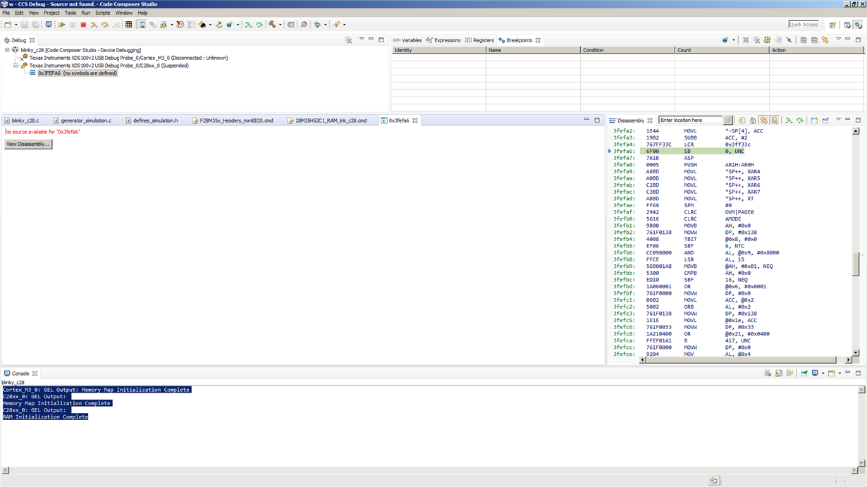
 I think I have problems with the boot mode but I saw the possible configurations of the switches and any of them allow me to boot de C28x from RAM.

Can anyone help me? Thanks in advance.

  • Hi,

    With emulator connected, device boots in EMULATION BOOT so please refer the emulation boot section of device TRM and make appropriate setting to BOOT the C28x from RAM.

    Regards,

    Vivek Singh

  • Hello.

    I do not know what emulation boot is. Could you please explain it deeper?

    Thank you.

  • Sorry, my mistake. On this particular device emulation boot is not supported. What code you are loading on M3 in this case? TRM has section "6.6.5.1 C-Boot ROM Boot-to-RAM Entry Point" which provides some info about this. Other thing you could try is instead of clicking on debug button, Ist launch the target configuration file and then connect to both the core and manually load the code on C28x and see if that works as expected.

    Vivek Singh
  • I could not make it work. The code I am loading on M3 is this:

    //###########################################################################
    // FILE:   Lab1_M3.c
    //###########################################################################
    //
    
    #include <string.h>
    
    #include "inc/hw_ints.h"
    #include "inc/hw_memmap.h"
    #include "inc/hw_nvic.h"
    #include "inc/hw_gpio.h"
    #include "inc/hw_types.h"
    #include "inc/hw_sysctl.h"
    #include "driverlib/debug.h"
    #include "driverlib/flash.h"
    #include "driverlib/ipc.h"
    #include "driverlib/interrupt.h"
    #include "driverlib/sysctl.h"
    #include "driverlib/gpio.h"
    
    extern unsigned long RamfuncsLoadStart;
    extern unsigned long RamfuncsRunStart;
    extern unsigned long RamfuncsLoadSize;
    
    //*****************************************************************************
    // Blink LED LD3
    //*****************************************************************************
    void main(void)
    {
        volatile unsigned long ulLoop;
    
        // Disable Protection
        HWREG(SYSCTL_MWRALLOW) =  0xA5A5A5A5;
    
        // Sets up PLL, M3 running at 75 MHz and C28 running at 150 MHz
        SysCtlClockConfigSet(SYSCTL_USE_PLL | (SYSCTL_SPLLIMULT_M & 0xF) |
                             SYSCTL_SYSDIV_1 | SYSCTL_M3SSDIV_2 |
                             SYSCTL_XCLKDIV_4);
    
    // Copy time critical code and Flash setup code to RAM
    // This includes the following functions:  InitFlash();
    // The  RamfuncsLoadStart, RamfuncsLoadSize, and RamfuncsRunStart
    // symbols are created by the linker. Refer to the device .cmd file.
        memcpy(&RamfuncsRunStart, &RamfuncsLoadStart, (size_t)&RamfuncsLoadSize);
        
    // Call Flash Initialization to setup flash waitstates
    // This function must reside in RAM
        FlashInit();                         
                          
        //  Send boot command to allow the C28 application to begin execution
        IPCMtoCBootControlSystem(CBROM_MTOC_BOOTMODE_BOOT_FROM_RAM);
    
        // Enable clock supply for GPIOC
        SysCtlPeripheralEnable(SYSCTL_PERIPH_GPIOC);
        
        // Give C28 control of Port C pin 6
        GPIOPinConfigureCoreSelect(GPIO_PORTC_BASE, 0x40, GPIO_PIN_C_CORE_SELECT);
    
        // Disable clock supply for the watchdog modules
        SysCtlPeripheralDisable(SYSCTL_PERIPH_WDOG1);
        SysCtlPeripheralDisable(SYSCTL_PERIPH_WDOG0);
        
        // Enable processor interrupts.
        IntMasterEnable();
    
        // Set up the Pin for LED LD3
        GPIOPinTypeGPIOOutput(GPIO_PORTC_BASE, GPIO_PIN_7);
        GPIOPinWrite(GPIO_PORTC_BASE, GPIO_PIN_7, ~0);
        
        while(1)
        {
            GPIOPinWrite(GPIO_PORTC_BASE, GPIO_PIN_7, 0);	// LD3 ON
            for(ulLoop = 0; ulLoop < 2750000; ulLoop++); 	// delay
            GPIOPinWrite(GPIO_PORTC_BASE, GPIO_PIN_7, ~0);	// LD3 OFF
            for(ulLoop = 0; ulLoop < 2750000; ulLoop++);	// delay
        }
    }

    I took this code from the F28M35x Workshop. The only thing I change was the next line:

    IPCMtoCBootControlSystem(CBROM_MTOC_BOOTMODE_BOOT_FROM_RAM);

    Originally it was:

    IPCMtoCBootControlSystem(CBROM_MTOC_BOOTMODE_BOOT_FROM_FLASH);

    I followed the guidelines given in this document, which is actually the F28M35x Whorshop:F28M35x_Workshop_3-0.pdf

  • I found that I had to force some object codes to be in the M0 RAM in the .cmd file to make the program load and execution from RAM work:

    ...
    boot : > RAMM0
    { F28M35x_SysCtrl.obj (.text:_InitPeripheralClocks)
    --library=rts2800_fpu32.lib<boot28.obj> (.text)
    F28M35x_SysCtrl.obj (.text:_InitSysCtrl)
    blinky_c28.obj (.text:_main)
    --library=rts2800_fpu32.lib<exit.obj> (.text)
    F28M35x_Gpio.obj (.text:_InitGpio)
    F28M35x_PieCtrl.obj (.text:_InitPieCtrl)
    --library=rts2800_fpu32.lib<cpy_tbl.obj> (.text)
    F28M35x_PieVect.obj (.text:_InitPieVectTable)
    --library=rts2800_fpu32.lib<memcpy.obj> (.text)
    --library=rts2800_fpu32.lib<args_main.obj> (.text)
    F28M35x_DefaultIsr.obj (.text:_EMPTY_ISR)
    F28M35x_DefaultIsr.obj (.text:_ADCINT1_ISR)
    F28M35x_DefaultIsr.obj (.text:_ADCINT2_ISR)
    F28M35x_DefaultIsr.obj (.text:_ADCINT3_ISR)
    --library=rts2800_fpu32.lib<pre_init.obj> (.text)
    --library=rts2800_fpu32.lib<startup.obj> (.text)
    }
    ...

    The problem is that one of them is the blinky_c28.obj (.text:_main) that contains the main function and when I add some code there it does not fit into the M0 RAM. I tried to put blinky_c28.obj (.text:_main) in another part of the RAM memory but the program did not even start when I did that. To avoid this, I moved all the extra code that I added to the main function to another function that was called from the main and I allow blinky_c28.obj (.text:_main) to be in M0 RAM . However, when I did that, the program did not work. It seems to be that the main function and all the functions that are called by it must be into the M0 RAM.
    So, the conclusion I get is that it is compulsory to put certain object codes in M0 RAM. Is this possible? It would mean that you can only execute a few instructions from the main function...
  • Hi, For RAM BOOT, entry point is 0x0 so that part should be in M0 but from there code should be able to branch to main() function which can be in other RAMs. In our example code, code_start function which is entry point is placed in codestart section, mapped in M0 (0x0). From code_start function execution branches to other code which is placed in .text section (not in M0).
    Please check F28M35x_CodeStartBranch.asm file in "device_support\f28m35x\v208\F28M35x_common\source" folder.

    Vivek Singh
  • Perfect. Taking into account this you are saying, I realized that the problem actually appears when I put sections in shared RAM (does this make sense?). I was using that RAM because the extra code I added did not fit into other memories (RAM L0 to RAM L1 are not enough).
  • Yes, that would be any issue. Master ownership for shared is with M3 by default. In M3 code you need to change the ownership of shared RAM to C28x before booting the C28x. You also have L2 and L3 RAMs (total 32KB of Lx RAMs) which can be used for code. Try that and if that's not enough then you have to use shared RAMs.

    Vivek Singh

  • Ok, I will try to give the shared RAM ownership to C28x because Lx RAMs are not enough (they are 32 KB, I guess). I found an example in Control Suite so I hope I will not have problems with that.
    However, there is something that calls my attention which is the fact that the shared RAM has the code written even though the C28x does not have the ownership of the shared RAM. I mean, in the .cmd I placed some code (.text) in shared RAM and it is there (I saw that in the Disassembly window) so... Should not the C28x be able to read it?
  • Only Writes and execution are blocked for non-master. Reads are never blocked. Similarly write access from debugger are never blocked so that code gets loaded and displayed even though master ownership is not with C28x.

    Following snapshot from TRM-

    Regards,

    Vivek Singh

  • Thanks. It finally worked. The key was to know how the M3 affects C28x access to shared RAM and that "Only Writes and execution are blocked for non-master"...
    Thanks, a lot.
  • Great. Glad to know it is working now.