Other Parts Discussed in Thread: CONTROLSUITE,
Tool/software: Code Composer Studio
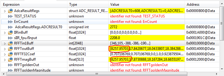
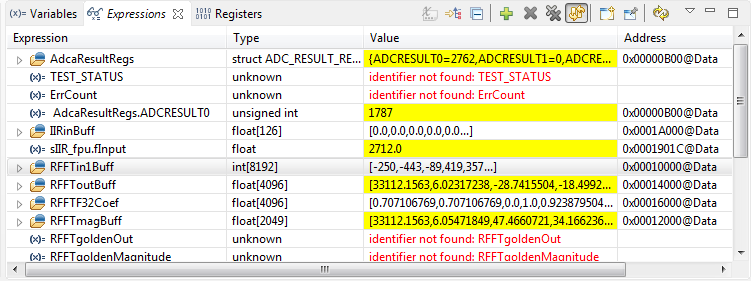
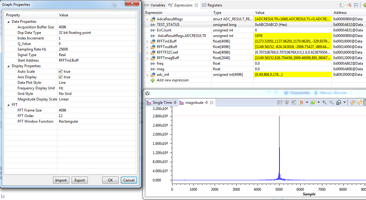
I am working with the example code 2837x_RFFT_ADC in controlSUITE with TMS320F28377D. The ADC is configured to work at 25,600 sample/sec, the ADC result is put into the RFFTin1Buff to calculate the frequency spectrum in microcontroller F28377D. The RFFT_STAGES is set to 12 (that mean FFT length=4096).
I use function generator to create a sinusoid 8KHz. The result is seem to be not correct. I have some questions need help.
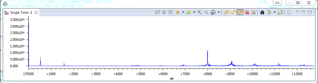
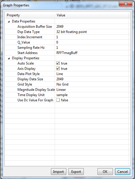
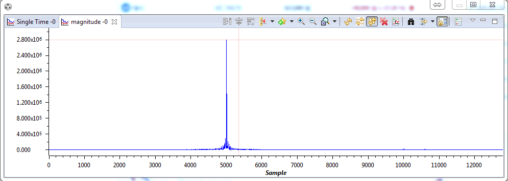
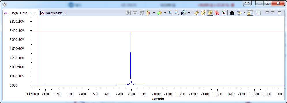
1--The first problem is the DC offset is to high as in the figure (I use Tools>Graph>Single Time to display the result of FFT calculation stored in RFFTmagBuff ). I used a IIR filter to remove the DC offset.
compare the result by using CCS to calculate FFT (Tools>Graph>FFT Magnitude)
2--The second problem is how to convert the unit of of result FFT magnitude, the y-axis in the graph,