


Part Number: TMS320F28335
Tool/software: Code Composer Studio
28335 CAN problem

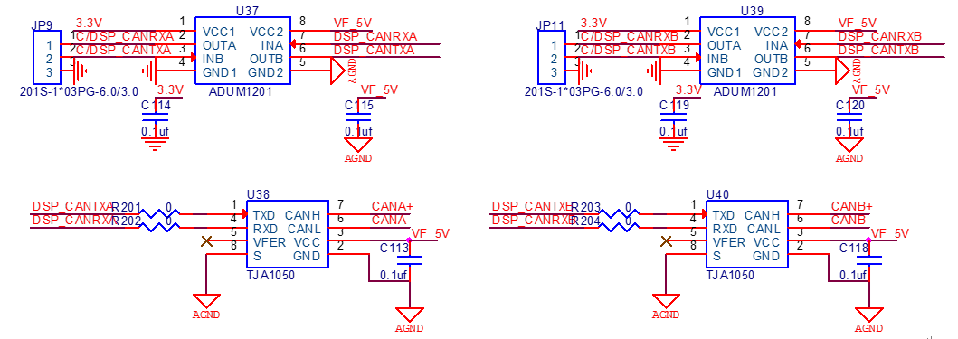
I have designed a board(called test board) with 28335 CAN interface,whose principle shows above. The serial port function and lights and other functions of the test board are normal, the emulator's connection of the test board is normal,too.
The CANA interface of the test board uses the pin GPIO18 and GPIO19, The CANB interface uses the pin GPIO12 and GPIO13.I have connected CANA + with CANB+, CANA- with CANB- ,and there was a 120Ω resistor in in parallel with CANA + and CANA-,in my CCS project, I set CANA to send 0X55555555 and 0XAAAAAAAA, CANB to receive and found abnormalities, which described as follows:
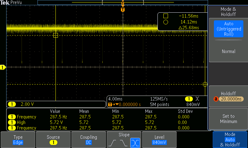
1、 I have bought a development board with 28335, too(called development board), and the same CCS project runs in the development board normally , the TXD waveform of the development board is shown below:

The CANA and CANB interface pin of the test board and the development board are same, but the CAN interface of the test board is abnormal, that the TA bit of the CANA can not be set.
2、 I have tried another GPIO like GPIO30 and GPIO31 ,the CANB transfer to the CANA, which performed the same.The waveform of the TXD pin is showen below:

3、 I have compared the difference between the test board and the development board, found that the chip screen is different, the test board chip lot number is G4A,and the development board chip lot number is CA, as shown below:

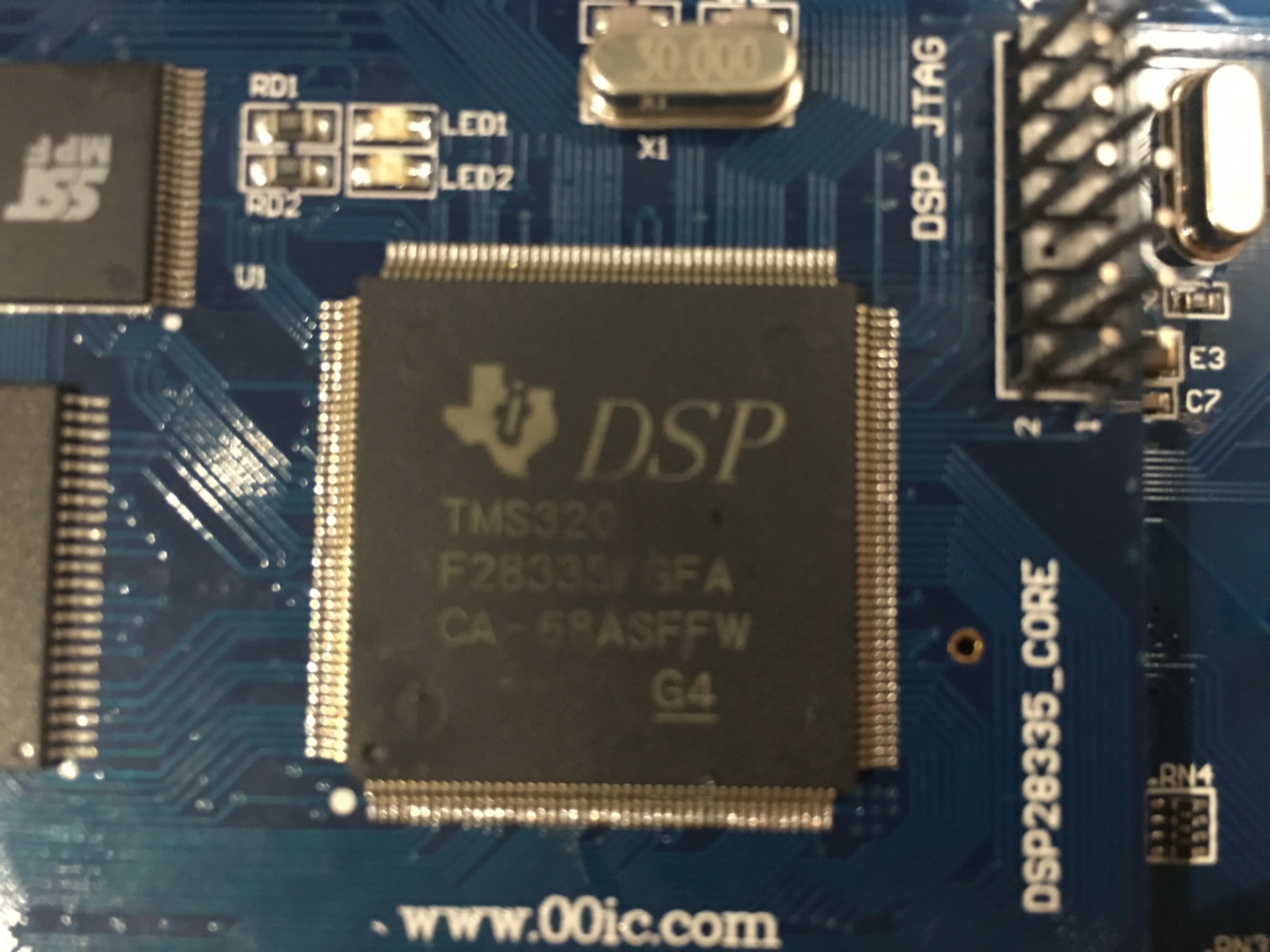
So I wonder why is that happen?
// TI File $Revision: /main/8 $
// Checkin $Date: August 10, 2007   09:04:22 $
//###########################################################################
// Filename: Example_28xEcan_A_to_B_Xmit.c
//
// Description: eCAN-A To eCAN-B TXLOOP - Transmit loop
//
// ASSUMPTIONS:
//
//    This program requires the DSP2833x header files.
//
//    Both CAN ports of the 2833x DSP need to be connected
//    to each other (via CAN transceivers)
//
//       eCANA is on GPIO19(CANTXA)  and
//                   GPIO18 (CANRXA)
//
//       eCANB is on GPIO20  (CANTXB)  and
//                   GPIO21 (CANRXB)
//
//    As supplied, this project is configured for "boot to SARAM"
//    operation.  The 2833x Boot Mode table is shown below.
//    For information on configuring the boot mode of an eZdsp,
//    please refer to the documentation included with the eZdsp,
//
//       $Boot_Table:
//
//         GPIO87   GPIO86     GPIO85   GPIO84
//          XA15     XA14       XA13     XA12
//           PU       PU         PU       PU
//        ==========================================
//            1        1          1        1    Jump to Flash
//            1        1          1        0    SCI-A boot
//            1        1          0        1    SPI-A boot
//            1        1          0        0    I2C-A boot
//            1        0          1        1    eCAN-A boot
//            1        0          1        0    McBSP-A boot
//            1        0          0        1    Jump to XINTF x16
//            1        0          0        0    Jump to XINTF x32
//            0        1          1        1    Jump to OTP
//            0        1          1        0    Parallel GPIO I/O boot
//            0        1          0        1    Parallel XINTF boot
//            0        1          0        0    Jump to SARAM       <- "boot to SARAM"
//            0        0          1        1    Branch to check boot mode
//            0        0          1        0    Boot to flash, bypass ADC cal
//            0        0          0        1    Boot to SARAM, bypass ADC cal
//            0        0          0        0    Boot to SCI-A, bypass ADC cal
//                                              Boot_Table_End$
//
// DESCRIPTION:
//
//    This example TRANSMITS data to another CAN module using MAILBOX5
//    This program could either loop forever or transmit "n" # of times,
//    where "n" is the TXCOUNT value.
//
//    This example can be used to check CAN-A and CAN-B. Since CAN-B is
//    initialized in DSP2833x_ECan.c, it will acknowledge all frames
//    transmitted by the node on which this code runs. Both CAN ports of
//    the 2833x DSP need to be connected to each other (via CAN transceivers)
//
//###########################################################################
// Original Author: HJ
//
// $TI Release: DSP2833x Header Files V1.10 $
// $Release Date: February 15, 2008 $
//###########################################################################

#include "DSP2833x_Device.h"     // DSP2833x Headerfile Include File
#include "DSP2833x_Examples.h"   // DSP2833x Examples Include File

#define TXCOUNT  100  // Transmission will take place (TXCOUNT) times..
#define LED1  GpioDataRegs.GPATOGGLE.bit.GPIO4
#define LED2  GpioDataRegs.GPATOGGLE.bit.GPIO5
#define LED3  GpioDataRegs.GPATOGGLE.bit.GPIO6
#define LED4  GpioDataRegs.GPATOGGLE.bit.GPIO7
// Globals for this example
long      i,j;
long      loopcount = 0;
volatile struct MBOX *Mailbox;
Uint32  ErrorCount;
Uint32  PassCount;
Uint32  MessageReceivedCount;

Uint32  TestMbox1 = 0;
Uint32  TestMbox2 = 0;
Uint32  TestMbox3 = 0;


void mailbox_check(int32 T1, int32 T2, int32 T3)
{
    if((T1 !=0x55555555 ) || ( T2 != 0xAAAAAAAA)|| ( T3 != 0x95555555))
    {
       ErrorCount++;
    }
    else
    {
       PassCount++;
    }
}


void main()
{

/* Create a shadow register structure for the CAN control registers. This is
 needed, since, only 32-bit access is allowed to these registers. 16-bit access
 to these registers could potentially corrupt the register contents. This is
 especially true while writing to a bit (or group of bits) among bits 16 - 31 */

   struct ECAN_REGS ECanaShadow;
    struct ECAN_REGS ECanbShadow;
// Step 1. Initialize System Control:
// PLL, WatchDog, enable Peripheral Clocks
// This example function is found in the DSP2833x_SysCtrl.c file.
   InitSysCtrl();

   EALLOW;
   GpioCtrlRegs.GPAMUX1.bit.GPIO4 = 0;
   GpioCtrlRegs.GPADIR.bit.GPIO4 = 1;
   GpioCtrlRegs.GPAMUX1.bit.GPIO5 = 0;
   GpioCtrlRegs.GPADIR.bit.GPIO5 = 1;
   GpioCtrlRegs.GPAMUX1.bit.GPIO6 = 0;
   GpioCtrlRegs.GPADIR.bit.GPIO6 = 1;
   GpioCtrlRegs.GPAMUX1.bit.GPIO7 = 0;
   GpioCtrlRegs.GPADIR.bit.GPIO7 = 1;
   EDIS;

// Step 2. Initalize GPIO:
// This example function is found in the DSP2833x_Gpio.c file and
// illustrates how to set the GPIO to it's default state.
// InitGpio();  // Skipped for this example

   // Just initalize eCAN pins for this example
   // This function is in DSP2833x_ECan.c
   InitECanGpio();

// Step 3. Clear all interrupts and initialize PIE vector table:
// Disable CPU interrupts
   DINT;

// Initialize the PIE control registers to their default state.
// The default state is all PIE interrupts disabled and flags
// are cleared.
// This function is found in the DSP2833x_PieCtrl.c file.
   InitPieCtrl();

// Disable CPU interrupts and clear all CPU interrupt flags:
   IER = 0x0000;
   IFR = 0x0000;

// Initialize the PIE vector table with pointers to the shell Interrupt
// Service Routines (ISR).
// This will populate the entire table, even if the interrupt
// is not used in this example.  This is useful for debug purposes.
// The shell ISR routines are found in DSP2833x_DefaultIsr.c.
// This function is found in DSP2833x_PieVect.c.
   InitPieVectTable();

// Interrupts that are used in this example are re-mapped to
// ISR functions found within this file.

// No interrupts used in this example.

// Step 4. Initialize all the Device Peripherals:
// This function is found in DSP2833x_InitPeripherals.c
// InitPeripherals(); // Not required for this example

   // In this case just initalize eCAN-A and eCAN-B
   // This function is in DSP2833x_ECan.c
   InitECan();
    ErrorCount = 0;
    PassCount = 0;
    // Step 5. User specific code:

/* Write to the MSGID field  */

   ECanaMboxes.MBOX10.MSGID.all = 0x95555555; // Extended Identifier

  ECanbMboxes.MBOX10.MSGID.all = 0x95555555; // Extended Identifier
/* Configure Mailbox under test as a Transmit mailbox */

   ECanaShadow.CANMD.all = ECanaRegs.CANMD.all;
   ECanaShadow.CANMD.bit.MD10 = 0;
   ECanaRegs.CANMD.all = ECanaShadow.CANMD.all;

   ECanbShadow.CANMD.all = ECanbRegs.CANMD.all;
   ECanbShadow.CANMD.bit.MD10 = 1;
   ECanbRegs.CANMD.all = ECanbShadow.CANMD.all;

/* Enable Mailbox under test */

   ECanaShadow.CANME.all = ECanaRegs.CANME.all;
   ECanaShadow.CANME.bit.ME10 = 1;
   ECanaRegs.CANME.all = ECanaShadow.CANME.all;

   ECanbShadow.CANME.all = ECanbRegs.CANME.all;
   ECanbShadow.CANME.bit.ME10 = 1;
   ECanbRegs.CANME.all = ECanbShadow.CANME.all;

/* Write to DLC field in Master Control reg */

   ECanaMboxes.MBOX10.MSGCTRL.bit.DLC = 8;

/* Write to the mailbox RAM field */

   ECanaMboxes.MBOX10.MDL.all = 0x55555555;
   ECanaMboxes.MBOX10.MDH.all = 0xAAAAAAAA;

   ECanbMboxes.MBOX10.MSGCTRL.bit.DLC = 8;

/* Write to the mailbox RAM field */

   ECanbMboxes.MBOX10.MDL.all = 0x55555555;
   ECanbMboxes.MBOX10.MDH.all = 0xAAAAAAAA;

/* Begin transmitting */


   for(i=0; i < TXCOUNT; i++)
   {

       ECanaShadow.CANTRS.all = 0;
       ECanaShadow.CANTRS.bit.TRS10 = 1;             // Set TRS for mailbox under test
       ECanaRegs.CANTRS.all = ECanaShadow.CANTRS.all;

       do
        {
        ECanaShadow.CANTA.all = ECanaRegs.CANTA.all;
        } while(ECanaShadow.CANTA.bit.TA10 == 0 );   // Wait for TA5 bit to be set..//如果线没有连接,如果线连接错误


       ECanaShadow.CANTA.all = 0;
       ECanaShadow.CANTA.bit.TA10 = 1;               // Clear TA5
       ECanaRegs.CANTA.all = ECanaShadow.CANTA.all;

       Mailbox = &ECanbMboxes.MBOX0 + 25;  //CANB读数据
       TestMbox1 = Mailbox->MDL.all; // = 0x (n is the MBX number)
       TestMbox2 = Mailbox->MDH.all; // = 0x (a constant)
       TestMbox3 = Mailbox->MSGID.all;// = 0x (n is the MBX number)
       mailbox_check(TestMbox1,TestMbox2,TestMbox3); // Checks the received data


       loopcount ++;
    }
      if(ErrorCount == 0)
          {
            asm("      ESTOP0"); // OK,数据校验正确
          }
          else
          {
            asm("      ESTOP0"); // ERROR,
          }


     //asm(" ESTOP0");  // Stop here
}

