This thread has been locked.

If you have a related question, please click the "Ask a related question" button in the top right corner. The newly created question will be automatically linked to this question.

TMS320F28027: Porblem with ADC precision

Part Number: TMS320F28027
Other Parts Discussed in Thread: LAUNCHXL-F28027

Hi, 

I have also posted this question here: 

https://electronics.stackexchange.com/questions/356934/how-to-improve-adc-accuracy?noredirect=1#comment856567_356934 

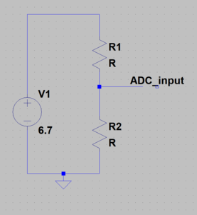
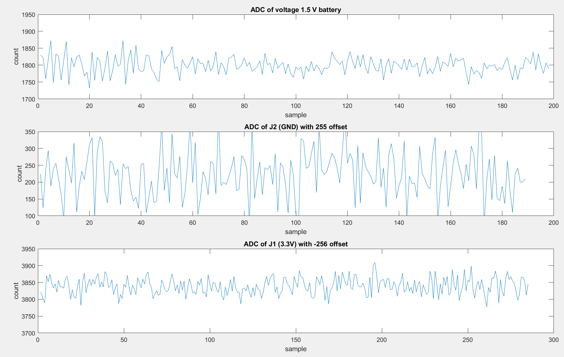
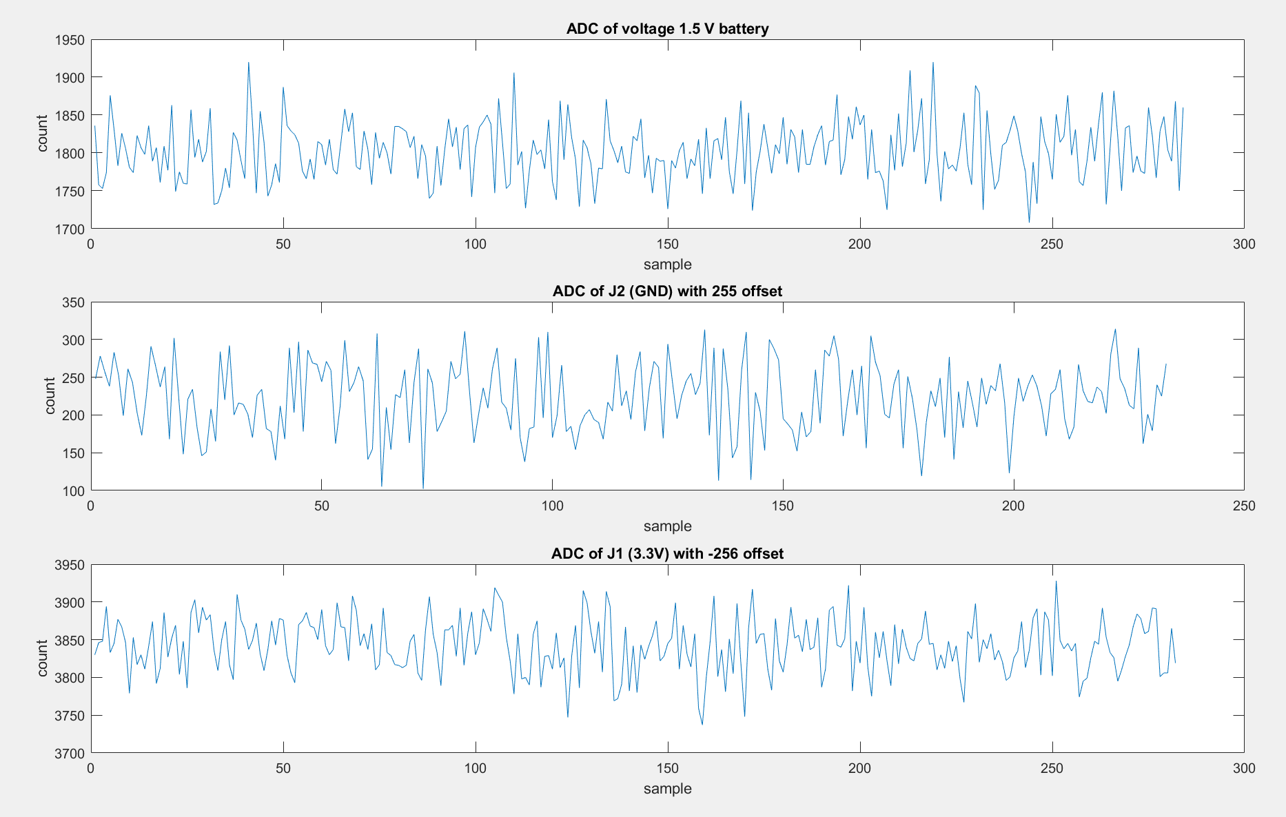
When running Example_F2802xAdcTempSensor, the returned values of the ADC differ by few counts between samplings, but when running the Example_F2802xAdcSoc program, the values returned vary easily by 100 counts. Values are taken at Vss adn ground of the MCU, and have also been taken with other stable sources includiong a battery. I changed the sampling window to match the window of the tempearture example. why are the values returned from the internally connected sensor more precise then does returned by otherwise? Pins are connected using jumper cables and are not soldered. 

  • Ray,

    What board are you using? Is it a TI EVM board or is it a custom board?

    A noisy external conversion usually points to a noisy signal source or a mismatch in the electrical characteristics of the circuit/connection at the ADC input vs the ACQPS settings. The ACQPS duration needs to satisfy the charge time of the sampling capacitor.

    From the datasheet:

    -Tommy

  • Hi Tommy, thanks for your help.

    I am using a Launchpad (LAUNCHXL-F28027).

    I am setting the window to 40 which seems high compared to the maximum of 64. I am testing the ADC with this circuit:

    The Battery is a 9 V Alkaline (I suppose with little resistance). In one test R1 and R2 are 1 KΩ and 5 kΩ, and in another 50 kΩ and 750 kΩ. I thought that matching the input resistance with the switch resistance would help and then though having the source resistance much greater. Nothing is returning stable results. 

  • I also tried with no resistance with a 1.5 volt battery, with the same results
  • Ray,

    Lower source resistance is better. For example, you would see better results by measuring the terminals of a 1.5V battery directly.

    The best setup for a voltage divider would be to buffer the resistor divider output using an op-amp with sufficient bandwidth and drive strength to charge the ADC sampling capacitor within your ACQPS window.

    If you can tolerate low bandwidth, you can also place a very large bulk capacitor (start around 4.7uF and experiment) at the voltage divider output so that the ADC sampling capacitor can be charged quickly by the lower impedance bulk capacitor rather than through the resistors.

    -Tommy
  • What values do you read back from the 1.5V battery? How are you connecting the 1.5V battery ground to the board ground?
  • Yes the board is connected to the same ground.

    results:

    data is output at 10 Hz. ADC is configured:

    ADC_setIntPulseGenMode(myAdc, ADC_IntPulseGenMode_Prior);               //ADCINT1 trips after AdcResults latch
        ADC_enableInt(myAdc, ADC_IntNumber_1);                                  //Enabled ADCINT1
        ADC_setIntMode(myAdc, ADC_IntNumber_1, ADC_IntMode_ClearFlag);          //Disable ADCINT1 Continuous mode
        ADC_setIntSrc(myAdc, ADC_IntNumber_1, ADC_IntSrc_EOC2);                 //setup EOC2 to trigger ADCINT1 to fire
        ADC_setSocChanNumber (myAdc, ADC_SocNumber_0, ADC_SocChanNumber_A0);    //set SOC0 channel select to ADCINA4
        ADC_setSocChanNumber (myAdc, ADC_SocNumber_2, ADC_SocChanNumber_A2);    //set SOC2 channel select to ADCINA2
        ADC_setSocTrigSrc(myAdc, ADC_SocNumber_0, ADC_SocTrigSrc_EPWM1_ADCSOCA);    //set SOC0 start trigger on EPWM1A, due to round-robin SOC0 converts first then SOC1
        ADC_setSocTrigSrc(myAdc, ADC_SocNumber_2, ADC_SocTrigSrc_EPWM1_ADCSOCA);    //set SOC2 start trigger on EPWM1A, due to round-robin SOC0 converts first then SOC1, then SOC2
        
        ADC_setSocSampleWindow(myAdc, ADC_SocNumber_0, ADC_SocSampleWindow_7_cycles);   //set SOC0 S/H Window to 7 ADC Clock Cycles, (6 ACQPS plus 1)
        ADC_setSocSampleWindow(myAdc, ADC_SocNumber_2, ADC_SocSampleWindow_40_cycles);   //set SOC2 S/H Window to 7 ADC Clock Cycles, (6 ACQPS plus 1)
       
        // Enable PWM clock
        CLK_enablePwmClock(myClk, PWM_Number_1);
    
        // Setup PWM
        PWM_enableSocAPulse(myPwm);                                         // Enable SOC on A group
        PWM_setSocAPulseSrc(myPwm, PWM_SocPulseSrc_CounterEqualCmpAIncr);   // Select SOC from from CPMA on upcount
        PWM_setSocAPeriod(myPwm, PWM_SocPeriod_FirstEvent);                 // Generate pulse on 1st event
        PWM_setCmpA(myPwm, 0x0080);                                         // Set compare A value
        PWM_setPeriod(myPwm, 0xFFFF);                                       // Set period for ePWM1
        PWM_setCounterMode(myPwm, PWM_CounterMode_Up);                      // count up and start
        CLK_enableTbClockSync(myClk);
    

    I didn't include the code but ADC A1, A3, A4, A6, and A7 are also configured

  • ADC A2 is the one being read
  • Ray,

    Let's work from the ground up.

    Disable all ADC channels except for A7. Then sample GND through A7 by using a jumper across J5-2 and J5-3. Be careful not to short 5V (J5-1) to GND. This should give you stable results near zero. For the sake of debug, you can program additional offset to ADCOFFTRIM if you only see zeros.

    Once this is proven to work, try to sample the 3.3V supply on J1-1 using A7. You should see stable conversions near 4095. Again, you can subtract from ADCOFFTRIM if the readings are stuck at 4095.

    After those two work, sample the 1.5V battery with A7 using the J5-2 and J5-3 pins directly.

    -Tommy
  • These are the results with:

    -only A7 initiated

    -J5-2 and J5-3 connected to the 1.5 V battery with J5-3 connected to J5-2

    -J5-3 connected to J5-2 with a 255 offset

    -J5-3 connected to J1-1 with a -256 offset

    -sampling window of 7

    - the plots all have a range of 250 counts


    Here are the same tests with a window of 40:

    The results of the 7 cycle window seem better than those for 40 cycle window. 

  • Ray,

    I found a F28027 LaunchPad here and am able to get GND readings through A7 where the results clustered within +/- 5 codes by using a shunt jumper across J5-2 and J5-3.  Replacing the shunt jumper with a short jumper wire widens the results to +/- 10 codes.  A longer cable gives me +/- 20 codes.  The error that you are seeing is possibly caused by the electrical parasitics of your setup.

    For good ADC performance, we usually place a capacitor on the ADC channel very close to the device.  This helps to filter out a lot of noise.  In the case of the LaunchPad, it looks like these capacitors were left off to keep the cost down.  Unfortunately, there's no easy way to add capacitors close to the device except with creative soldering.

    The easiest workaround here would be to oversample your input signal and average the results.  That approach is usually very effective.

    -Tommy

  • Thanks a lot for the help Tommy.