This thread has been locked.

If you have a related question, please click the "Ask a related question" button in the top right corner. The newly created question will be automatically linked to this question.

TMDSDOCK28379D: ADC, ePWM Pin capabilities and more

Part Number: TMDSDOCK28379D

Hi,

I'm currently making a breakout board for motor control applications with the specified control card and I had some general questions:

- Are there any other pins that can be configured as ADC inputs? I see from the attached pinout diagram that I can use select pins in the range of pins 9 through 42 (excluding GND pins). This sums up to 24 ADC pins, but I am wondering if it is possible for me to access more than 24 ADC's (perhaps using software) and if so, what pins are those?

- Which pins can be used as ePWM outputs? Same question as above, I have found 16 of the PWM pins, and am wondering if there are other pins that are configurable to become ePWM or PWM pins so that I can use more than 16 of these types of signals. On the datasheet, it says there are 24 PWM channels, 16 HRPWM channels; what pins are those that are hiding from the attached pinout diagram? 

- With respect to the ADC pins again, is there a special functionality with pins ADC14 and ADC15? Just curious why they have a different naming format from all the other ADC pins and if I can use them as normal ADC pins.

- Are there any particular grounds that are intended to be used as analog grounds? All of the grounds are internally connected on the control card, so I'm wondering if I can use any ground I want as a dedicated "AGND" or if this matter at all and I can just connect the AGND and GND pins on my board I'm making since they will all eventually get shorted inside the control card anyways. 

- Can any pin I want be configured as TZ pins, and if so do they all share the same functionality? I ideally want to use a quantity that is equal to half of the number of total pwm pins. For example if there are 16 PWM pins I want 8 eCAP pins. 

- Can I use any other pins as eCAP pins other than the four specified on GPIO pins 24-27? I ideally want to use a quantity that is equal to half of the number of total pwm pins. For example if there are 16 PWM pins I want 8 eCAP pins.

- Does the reset pin (pin 120) on the board clear the ram? If I write a program to the device and click the reset pin, am I going to have to reflash my program again, or does it work similar to an arduino? 

I have attached the pinout diagram I used to assemble my board as well as my current schematic of the pins I am using if that helps clear up what I am talking about.
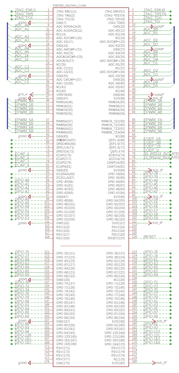
6505.TMDSCNCD28377D_180cCARD_pinout_R1_3.pdf

  • Hi Sean,

    I think quite a few of these questions can be found in either the datasheet or TRM for this part.

    The datasheet is here, and will answer questions about "what pins are there, how are they mux'ed, etc":
    www.ti.com/.../datasheet

    For instance, you can find the total ADC channel count in the device comparison table:
    www.ti.com/.../device-comparison

    And a list of the specific pins and functions in the signal descriptions table:
    www.ti.com/.../terminal-configuration-and-functions

    The TRM is here:
    www.ti.com/.../spruhm8g.pdf

    And should answer deeper questions about how the device and modules function.
  • Sean,

    The ADC pins do not go through the GPIO multiplexer and are fixed as specified in the data sheet. ADCIN14 and ADCIN15 are common to all four ADC units. The ePWM pins are selected with the GPIO multiplexer, and the TZ pins are assigned with the Input X-Bar (from the GPIO pins). Likewise, the inputs to the eCAPs are configured with the Input X-Bar. I suggest looking at the following workshop:

    processors.wiki.ti.com/.../C2000_Multi-Day_Workshop

    See module 5 for more details about the GPIO and Input X-Bar structure. You might be interested in looking at the GPIO.c and Xbar.c files in lab 7.

    I hope this helps. If this answers your question, please click the green "Verified Answer" button. Thanks.

    - Ken
  • Both answers helped me a lot.

    Just for clarification, I can use any GPIO pins for any TZ pins I want, as well, I can use any GPIO pins for any ECAP pins I want?

    Just curious if there are specific GPIO pins I need to use for each specific PWM module or if I am going to run into any problems there. For example an issue I want to avoid is if GPIO pin 50, if configured as a TZ (or ECAP) pin MUST be used with EPWM module B.

    I've looked through the technical reference manual and I see no such limitations, other than for example how many TZ pins you could use per module. Just want to make sure I'm not printing a board that will have to get immediately redone.

    Thanks again!
  • Sean,

    The GPIO pins for the TZ and ECAP are selected by the INPUT X-BAR. See the F28379D TRM figure 8-1 on page 1138. TZ1 - TZ3 are on the INPUT X-BAR inputs 1-3 and the ECAPs are on inputs 7-12, where any GPIO pin can be selected. For the EPWM modules, any TZ can be connected to any or multiple EPWM modules. However, each ECAP has a specific input used for each ECAP. For example, when using ECAP1 the signal is from input 7.

    I recommend reviewing the following workshop and lab code (Xbar.c) to better understand the X-BARs:

    processors.wiki.ti.com/.../C2000_Multi-Day_Workshop

    I hope this helps. If this answers your question, please click the green "Verified Answer" button. Thanks.

    - Ken
  • Ah alright, thanks! So basically any ePWM module can use any GPIO pin for the requested features, and then all the configuration is done through software. I checked out the code and it seems quite straightforward to set up.