


Part Number: TMS320F28069
Hello,
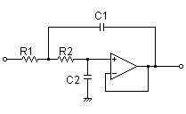
I am working on my own inverter project. I want to generate Sine wave sync with Grid wave. I am using Sallen Key Low Pass Filter out of PWM pins. R1 = 51K , R2 = 30K, C1=10nF, C2=4nF.
My SPLL coeffs.
spll_obj->lpf_coeff.B0_lf=(float32)(1055.625014);
spll_obj->lpf_coeff.B1_lf=(float32)(-1044.375014);
spll_obj->lpf_coeff.A1_lf=(float32)(-1.0);
The output of filter give me a sine wave with high distorsion. I tried a lot of things like change coeffs , change the sampling frequency. But it didn't go well.
I add my code and pictures of outputs. In the scope picture yellow is my SPLL output and other one is grid. What is the problem.
And what is the natural frequency in excel file????

void adcTimerFxn(void)
    {
//50 KHz ISR
        AdcRegs.ADCSOCFRC1.all=0xFFFF;
        while(AdcRegs.ADCINTFLG.bit.ADCINT1 == 0) {}
        AdcRegs.ADCINTFLGCLR.bit.ADCINT1 = 1;

       spll1.AC_input = ((float32)AdcResult.ADCRESULT9-2048)/(float32)2048; // SPLL call
       SPLL_1ph_F_MACRO(spll1);
       temp = (((spll1.sin[1])+1.0)/2)*EPwm2Regs.TBPRD;
       EPwm2Regs.CMPA.half.CMPA =EPwm2Regs.TBPRD - _IQsat(temp,EPwm2Regs.TBPRD,0);

    }

