This thread has been locked.

If you have a related question, please click the "Ask a related question" button in the top right corner. The newly created question will be automatically linked to this question.

LAUNCHXL-F28379D: 5 volt external supply LaunchPad F28379D

Part Number: LAUNCHXL-F28379D

Hi all, 

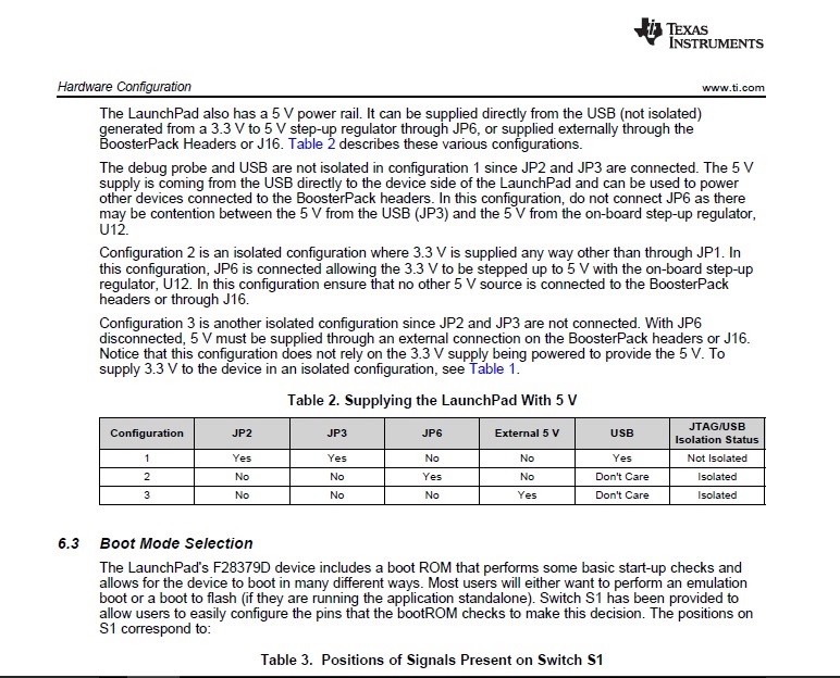
I am trying to run my Launchpad from an external 5V power supply(without a USB plugged in) using the Configuration 3.(Supplying the LaunchPad With 5V) as mentioned in the LaunhXL User Guide.

More Specifically I've removed the JP1,JP2,JP3 jumpers and supply the board with 5V using the J16 connector. The Launchpad didn't seem to work as expected.

After this I've tried every possible configuration with the JP1,JP2,JP3 jumpers and again nothing happened.

I even tried to connect the Launchpad with a "power only" USB cable having the same result one more time.

THE ONLY TIME my Launchpad seemed to works properly was when I plugged it via USB to my Laptop.

What I have to do in order to supply externally my Launchpad with 5V without having it plugged in to PC USB port?

Any answer will be appreciated!

  • Hi,

    It sounds like what you want to do is have the C2000 to boot-from-flash in this configuration.

    How is S1's position 3 configured?  Can you try it in the down position and see if that helps?


    Thank you,
    Brett

  • Thank you for your quick response. I've managed to run a simple program that flashes the blue onboard LED and send a message through SCIA on the USB connector by using the settings that you recommended.
    The main problem occurs when I am trying to use the CANB/CANA modules. In that case the  LED continues to blink and the SCIA configuration is functional BUT the CANA/CANB module does not transmit anything.
    Everything run smoothly when I plugged the Launchpad in to my Laptop.

    I can't figure it out what am I doing wrong.

    Best regards

  • Kyriakos,

    I am not sure I understand your issue.

    can you show a table with your jumper settings and power supply along with the result of that configuration?

    The MCU(target) side of the board requires that 3.3 V is supplied either through the BoosterPack headers, J10, or across the isolation boundary through J1. without 3.3 V, the MCU will not operate as it is not receiving power. If you only connect 5 V to the MCU side, the device will not receive 3.3 V power.

    When the USB cable is connected, the 5 V from the USB is regulated down to 3.3 V for the XDS100 debugger. If J1 is shorted, 3.3 V will be supplied to the target.

    Please let me know if you have additional clarifications. When these power jumpers are incorrectly set, usually the MCU is either unpowered or possibly powered by two sources in contention. I would not expect partial operation as you described in your most recent reply.

    Thanks,
    Mark
  • Hi  Mark,

    Eventually  by sharing a common reference voltage between my LaunchPad and the CANbus to USB interface I was able to solve my problem with the following configurations:

    CONFIG_1:

    JP1: shorted

    JP2: shorted

    JP3: shorted

    JP4: shorted 

    JP5: shorted

    JP6: open circuit

    J16: 5V external supply

    S1: all switces are in the same position

    CONFIG_2:

    JP1: open circuit

    JP2: open circuit

    JP3: open circuit

    JP4: shorted 

    JP5: shorted

    JP6: open circuit

    J10: 3V external supply

    S1: all switces are in the same position

    Nevertheless I didn't manage to use the Launchpad with a 5V external supply and isolate the debug probe.

    Thank you for any help you can offer 

  • Kyriakos,

    for COFIG_1, you will be having some contention on 5 V between the USB driving 5 V and the external supply. This case has 3.3V coming from the USB, through JP1 and should work if you either A: diconnect the USB cable, so only the 5V input from the external supply is connected, or B: disconnect the external supply, leaving only power through 5V from the USB.

    in CONFIG_2, you should be operating properly as the MCU (and the CAN transciever) is receiving 3.3 V from the external Supply. There is no 5 V on your target side. If you do require 5 V, you canshort JP6. This will step 3.3 V up to 5 V with U12. You should also be able to connect to the debugger without any issues since it is electrically isolated from the target.

    Do you require 5V on the Target side?
  • Thank you for your quick response!

    My ultimate goal is to supply the target externally with 5V  and isolating the Debug probe as described in the User's Guide(page 10, Configuration 3). But this configuration doesn't seem to work.

  • Kyriakos,

    Supplying the target with 5 V only will not work and was never intended to work. I will have the documentation updated to be more clear on this topic.The section you are referencing is only referring to supplying 5 V to the +5V0 rail on the board. There should be another column on in Table 2, titled: F28379D power status. 

    Configuration ... F28379D
    Power status
    1 ... If JP1 is shorted, F28379D is powered
    2 ... Requires external 3.3 V
    3 ... Requires external 3.3 V

    For device operation while using the isolated JTAG, the target side of the PCB requires 3.3 V. There is no target-side circuitry to step down 5 V to 3.3 V, so it must be supplied externally.

    Thanks,
    Mark

  • Hi Mark,

    Thank you for your support!

    Best regards
    Kyriakos
  • Glad to be of assistance. Please don't hesitate to post again in the future if you have any new questions.

    -Mark