This thread has been locked.

If you have a related question, please click the "Ask a related question" button in the top right corner. The newly created question will be automatically linked to this question.

DRV8312-C2-KIT: BLDC with Hall-effect using DRV8312-C2-KIT with F28069MPZT MCU

Part Number: DRV8312-C2-KIT
Other Parts Discussed in Thread: INSTASPIN-BLDC, TMS320F28069, DRV8312, CONTROLSUITE, ASH

Hello ,

I am working with DRV8312-C2-Kit (F28069MPZT MCU) and need to control the speed of BLDC with Hall-effect sensor and monitoring the current as well .

I powered up the kit as directed by "DRV8312 Digital Motor Control Kit Quick Start Guide". I have tried   "BLDC_Sensored" ,"GUI_project_InstaSPIN_BLDC" ,"InstaSPIN_BLDC" projects with F2806x configuration on CCSV7 ,Compile and run , run the GUI(C:\ti\controlSUITE\development_kits\DRV8312-C2-KIT_v128\~GUI\ ….DRV8312GUIv5.exe  || InstaSPIN-BLDC_GUI_DRV83xx_v104.exe ) as well which I got access to those from "C:\ti\controlSUITE\development_kits\DRV8312-C2-KIT_v128" . None of those could connect to Piccolo TMS320F28069 Isolated controlCARD and make the motor run   ! Even I tried with F2803x config(I know is wrong) but at least turned the fault status green which is odd .

I am confused as many options are available on that folder and I would like to know which one is suitable for my application .Could you please simply direct me what firmware that I should import on my code composer to run on the chip and what GUI can communicate with that ? Also I would like to know ,is it possible to get the source code of the GUI !?

-Also I would like to run 12V motor instead 24V motor with this Dev Kit .Is it possible ? I didn’t understand what is the purpose of JP1 ! (current of 12VDC motor is 1.2A Max )

Thanks

Ashkan Golestani

  • Please follow these board settings:

    • a. TMDSCNCD28069MISO

    i. SW1: UP-UP

    ii. SW2: DOWN-DOWN

    iii. SW3: UP-UP

    • b. DRV8312_REVD

    i. JP1: VR1 - Middle

    ii. JP2: Populated

    iii. M1: High-Middle

    iv. All three toggle switches in the middle (MCU) position

    v. Motor Phase Wires to MOA, MOB, MOC

    vi. DC Voltage to J9 or PVDDIN

    You are able to run the 12V motor with this kit, no problem. JP1 is a jumper to choose either on-board buck regulation for 12V input or external regulated 12V input. We are not able to provide the source that ships on the device for the GUI.

    As of now, we recommend using Code Composer Studio itself to run the InstaSPIN_BLDC labs on F2806x devices. There are no existing labs to support F2806x for use with the GUI. Instead, I would use this lab: C:\ti\controlSUITE\development_kits\DRV8312-C2-KIT_v128\BLDC_Sensored

    to run a BLDC with hall sensor drive on F28069MISO control card

    Sean

  • Hello Sean,

    Thanks for quick reply .

    As I mentioned I have no problem with hardware setup and I powered up the kit as directed by "DRV8312 Digital Motor Control Kit Quick Start Guide". Anyway ,Thanks again for direction .

    Sounds like I can’t Use the GUI !

    Should I use the same connector to apply 12V DC supply instead 24VDC ?! Or using PVDD  2 pin Blue connector ?


    Thanks

    Ash

  • As you directed to use the "C:\ti\controlSUITE\development_kits\DRV8312-C2-KIT_v128\BLDC_Sensored ".

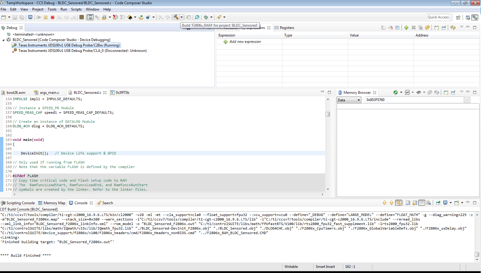
    I did import the project ,Build correctly with F2806x_RAM config .  debug and run the project .

    Unfortunetly Heart bit of the board dont function that It means Program has some issues !

  • For the heart-beat try this:

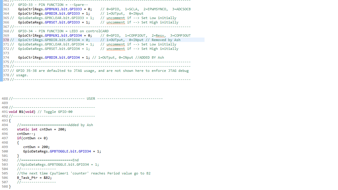
    In file "BLDC_Sensored-DevInit_F2806x.c", line 370, change to...

    GpioCtrlRegs.GPBDIR.bit.GPIO34 = 1; // 1=OUTput, 0=INput

    In file "BLDC_Sensored.c", around line 494, in Function void B1(void), insert following lines...

    static int cntDwn = 200;
    cntDwn--;
    if(cntDwn <= 0)
    {
       cntDwn = 200;
       GpioDataRegs.GPBTOGGLE.bit.GPIO34 = 1;
    }
    

  •  Thanks again .

    I made the modification . Red LED is solid ON . Timer of 5 ms dont Run !!!

    Placed brakepoint inside the B1, never hit .

    Ash

  • Hello,

    Could you please direct me how to power 12V motor ?

    I've applied 12v to the PVDDIN instead 24V to J9 ,Development kit can't power on (LEDs are off) !

    Please help me on this .

    By the way ! I've fixed the Hearbeat by call the B state machine functions.Originally only A series were on call by pointers .Keep it for your record. 

    Thanks

    Ash

  • Please leave JP1 to use middle+left, designated at VR1, if you're using the on-board buck to provide 12V supply. Supply PVDDIN with 24V

    Sean
  • As I asked , I want to power the Devkit with 12 Volt from desk power supply only . I don't have 24 volt on my future design and I am not asking to use on-board Buck converter eventually !
    Ash

  • To provide GVDD an external 12V reference, set JP1 to middle-right (towards +12V), and connect your desk supply leads to the "AUX 12V" header adjacent to JP1. PVDD uses the voltage presented to either J9 or the PVDDIN connectors. So you'll need to provide the 12V leads to both if you want to use the desk supply for both controller power and driver power.

    Sean

  • Thanks ,

    Yes I did figure it out  yesterday . Also applying 12V to jumper style connector middle of the board is not usual and it is awkward!

    BTW,Thanks for support .

    Ash