Part Number: TMS320F280049
Other Parts Discussed in Thread: C2000WARE
Tool/software: Code Composer Studio
Hi everyone,
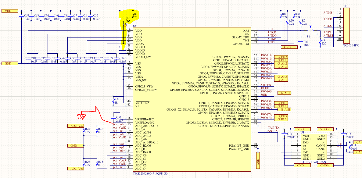
I have a custom board for the TMS320F280049 microcontroller, the schematic is attached to this thread. I am using the example projects with the C200ware, which supports the new microcontroller. It looks like the header files are intended to be used with a development board or something.
I have tried the interrupt project, LED project according to "F28004x_DEV_USER_GUIDE.pdf". The projects build and load, however, they debugger does not show anything. For example, the timers (counters) do not increment. Does anyone have a blank project or a PWM or timer project with all the general device header files. Any ideas?
//#############################################################################
//
// FILE: timer_ex1_cputimers.c
//
// TITLE: CPU Timers Example
//
//! \addtogroup bitfield_example_list
//! <h1> CPU Timers </h1>
//!
//! This example configures CPU Timer0, 1, and 2 and increments
//! a counter each time the timer asserts an interrupt.
//!
//! \b External \b Connections \n
//! - None
//!
//! \b Watch \b Variables \n
//! - CpuTimer0.InterruptCount
//! - CpuTimer1.InterruptCount
//! - CpuTimer2.InterruptCount
//!
//
//#############################################################################
// $TI Release: F28004x Support Library v1.03.00.00 $
// $Release Date: Thu Dec 7 18:46:47 CST 2017 $
// $Copyright:
// Copyright (C) 2017 Texas Instruments Incorporated - http://www.ti.com/
//
// Redistribution and use in source and binary forms, with or without
// modification, are permitted provided that the following conditions
// are met:
//
// Redistributions of source code must retain the above copyright
// notice, this list of conditions and the following disclaimer.
//
// Redistributions in binary form must reproduce the above copyright
// notice, this list of conditions and the following disclaimer in the
// documentation and/or other materials provided with the
// distribution.
//
// Neither the name of Texas Instruments Incorporated nor the names of
// its contributors may be used to endorse or promote products derived
// from this software without specific prior written permission.
//
// THIS SOFTWARE IS PROVIDED BY THE COPYRIGHT HOLDERS AND CONTRIBUTORS
// "AS IS" AND ANY EXPRESS OR IMPLIED WARRANTIES, INCLUDING, BUT NOT
// LIMITED TO, THE IMPLIED WARRANTIES OF MERCHANTABILITY AND FITNESS FOR
// A PARTICULAR PURPOSE ARE DISCLAIMED. IN NO EVENT SHALL THE COPYRIGHT
// OWNER OR CONTRIBUTORS BE LIABLE FOR ANY DIRECT, INDIRECT, INCIDENTAL,
// SPECIAL, EXEMPLARY, OR CONSEQUENTIAL DAMAGES (INCLUDING, BUT NOT
// LIMITED TO, PROCUREMENT OF SUBSTITUTE GOODS OR SERVICES; LOSS OF USE,
// DATA, OR PROFITS; OR BUSINESS INTERRUPTION) HOWEVER CAUSED AND ON ANY
// THEORY OF LIABILITY, WHETHER IN CONTRACT, STRICT LIABILITY, OR TORT
// (INCLUDING NEGLIGENCE OR OTHERWISE) ARISING IN ANY WAY OUT OF THE USE
// OF THIS SOFTWARE, EVEN IF ADVISED OF THE POSSIBILITY OF SUCH DAMAGE.
// $
//#############################################################################
//
// Included Files
//
#include "F28x_Project.h"
//
// Function Prototypes
//
__interrupt void cpuTimer0ISR(void);
__interrupt void cpuTimer1ISR(void);
__interrupt void cpuTimer2ISR(void);
//
// Main
//
void main(void)
{
//
// Initialize device clock and peripherals
//
InitSysCtrl();
//
// Initialize GPIO
//
InitGpio();
//GPIO_SetupPinMux(31U, GPIO_MUX_CPU1, 0);
//GPIO_SetupPinOptions(31U, GPIO_OUTPUT, GPIO_PUSHPULL);
//
// Disable CPU interrupts
//
DINT;
//
// Initialize the PIE control registers to their default state.
// The default state is all PIE interrupts disabled and flags
// are cleared.
//
InitPieCtrl();
//
// Disable CPU interrupts and clear all CPU interrupt flags
//
IER = 0x0000;
IFR = 0x0000;
//
// Initialize the PIE vector table with pointers to the shell Interrupt
// Service Routines (ISR)
//
InitPieVectTable();
//
// Map ISR functions
//
EALLOW;
PieVectTable.TIMER0_INT = &cpuTimer0ISR;
PieVectTable.TIMER1_INT = &cpuTimer1ISR;
PieVectTable.TIMER2_INT = &cpuTimer2ISR;
EDIS;
//
// Initialize the Device Peripheral. For this example, only initialize the
// Cpu Timers.
//
InitCpuTimers();
//
// Configure CPU-Timer 0, 1, and 2 to interrupt every second:
// 100MHz CPU Freq, 1 second Period (in uSeconds)
//
ConfigCpuTimer(&CpuTimer0, 100, 1000000);
ConfigCpuTimer(&CpuTimer1, 100, 1000000);
ConfigCpuTimer(&CpuTimer2, 100, 1000000);
//
// To ensure precise timing, use write-only instructions to write to the
// entire register. Therefore, if any of the configuration bits are changed
// in ConfigCpuTimer and InitCpuTimers, the below settings must also be
// be updated.
//
CpuTimer0Regs.TCR.all = 0x4000;
CpuTimer1Regs.TCR.all = 0x4000;
CpuTimer2Regs.TCR.all = 0x4000;
//
// Enable CPU int1 which is connected to CPU-Timer 0, CPU int13
// which is connected to CPU-Timer 1, and CPU int 14, which is connected
// to CPU-Timer 2
//
IER |= M_INT1;
IER |= M_INT13;
IER |= M_INT14;
//
// Enable TINT0 in the PIE: Group 1 interrupt 7
//
PieCtrlRegs.PIEIER1.bit.INTx7 = 1;
//
// Enable global Interrupts and higher priority real-time debug events
//
EINT;
ERTM;
//
// IDLE loop. Just sit and loop forever (optional).
//
while(1)
{
}
}
//
// cpuTimer0ISR - CPU Timer0 ISR with interrupt counter
//
__interrupt void cpuTimer0ISR(void)
{
CpuTimer0.InterruptCount++;
//
// Acknowledge this interrupt to receive more interrupts from group 1
//
PieCtrlRegs.PIEACK.all = PIEACK_GROUP1;
}
//
// cpuTimer1ISR - CPU Timer1 ISR with interrupt counter
//
__interrupt void cpuTimer1ISR(void)
{
//
// The CPU acknowledges the interrupt
//
CpuTimer1.InterruptCount++;
}
//
// cpuTimer2ISR CPU Timer2 ISR with interrupt counter
//
__interrupt void cpuTimer2ISR(void)
{
//
// The CPU acknowledges the interrupt
//
CpuTimer2.InterruptCount++;
}
//
// End of file
//