This thread has been locked.

If you have a related question, please click the "Ask a related question" button in the top right corner. The newly created question will be automatically linked to this question.

LAUNCHXL-F28379D: How to calculate the angular velocity using eQEP?

Part Number: LAUNCHXL-F28379D

Hi All,

I am trying to implement a closed-loop speed controller using encoders. My encoders have only 3 pins. (PWR, GND, and SGN)

I fed the output from the eQEP (QPOSCNT) to a GPIO pin (digital output) to display the signal using my oscilloscope. 

My measurements showed that the period of the QPOSCNT signal is changing as the duty cycle of the PWM signals changes (as expected).

At 20% duty cycle: the period of QPOSCNT is 344ms.

At 40% duty cycle: the period of QPOSCNT is 47.20ms.

Now, how can I calculate the angular velocity from the QPOSCNT signal? 

My guess is to configure a rising or falling edge interrupt, count the number of edges in a fixed period (e.g. 1 second) and then calculate the angular velocity using the formula below:

w_rpm = (N/Nppr)*(60sec/1min)/T

where N is the number of edges,  Nppr is the number of slots in the encoder (mine has 10), and T is 1.

But if this is the correct way of doing it, why are we using the eQEP in the first place? I could have triggered an interrupt directly from the SGN pin of the encoder (which also outputs a square wave whose frequency is proportional to the w_rpm.)

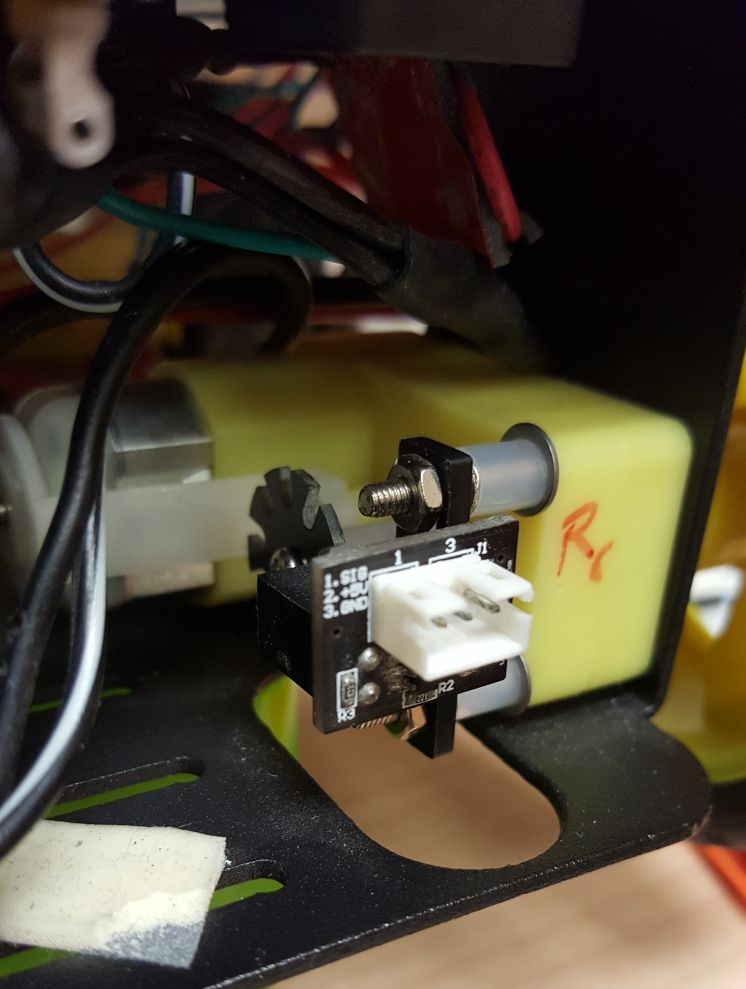
Image of my encoders: 

  • Hi Canberk,

    What exactly are you connecting to eQEP inputs? Is it the signal coming from encoder - to which eQEP port did you connect this to?
    QEP also can determine the direction (Depending on the 2 inputs A and B coming from the encoder) and measure the change in position accordingly.
    From your description, your encoder seems to generate SGN signal indicating the movement?
    Are you interested in just capturing the duty cycle of this signal?

    -Bharathi.
  • QEP gives the incremental count from an index point, that represents the angle from the index. Between consecutive QEP reads, it gives incremental angle information that is representative of the angular speed. Speed can be derived out of position information in more than one way. Angle information is needed for doing FOC. Not sure what you want to achieve.
  • Hi Canberk, Were you able to resolve the issue?
  • Hi Subrahmanya, No, not yet. I am running the robot in open loop at the moment. But I want to run it in closed-loop if I can solve this issue. Do you have any suggestions? 

  • Typically QEPs have more counts per rotation than 10. At lower speeds, one could measure the time difference(T) between the signal edges (rising to falling or vice versa) and based on this, speed can be calculated using the formula (PI / Nppr) / T or (2.PI / Nppr)/ T if T is captured between two rising edges or two falling edges.

    At high speeds, one could use the difference in counts between two successive periodic time window. But to do this, a higher count will give better result.

    If you do FOC, you need angle information for Park and inverse Park transforms as well for which more Nppr is needed. 

    But your application seem to have only one signal and has Nppr =10. I guess it does not fall in the usual QEP use case. I recommend you to review the QEP peripheral interface methodology from our guide one more time to see how to fit your application. 

    http://www.ti.com/lit/ug/sprug05a/sprug05a.pdf