This thread has been locked.

If you have a related question, please click the "Ask a related question" button in the top right corner. The newly created question will be automatically linked to this question.

CCS/TMS320F28035: About piccolo 2803x interrupt configuration doubt. Thanks~

Part Number: TMS320F28035

Tool/software: Code Composer Studio

I want to change EPWM interrupt entry determined by different situation (for loops), just like:
   1.  if(A situation)  then EPWM --> ISR1, then disable ISR2
   2.  if(B situation)  then EPWM --> ISR2, then disable ISR1
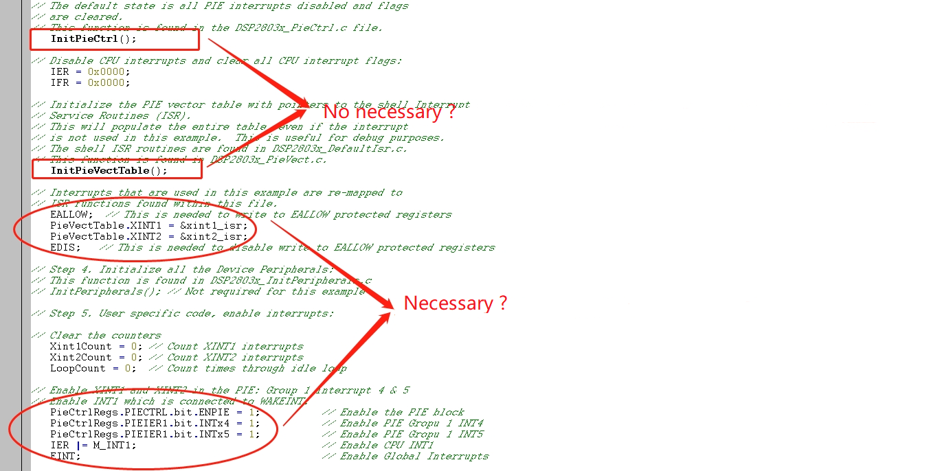
so, my question is, when change the entry of EPWM from ISR1 to ISR2, must I re-configure the interrupt whit initializing InitPieCtrl(), InitPieVectTable() ? Or can I just change PieVectTable of EPWM from ISR0 to ISR1 ?
Thanks!
  • User,

    First, to use these interrupts the PIE needs to be initialized and enabled. This is performed by the InitPieCtrl() and InitPieVecTable(). Next, each peripheral function/interrupt has a unique location in the PIE table. The vector locations are fixed. So, if you are using one common peripheral (in your case the same ePWM) then the decision logic should be done in that ISR.

    To learn more about the PIE interrupts, please see module 4 and lab 5 in the following workshop:

    processors.wiki.ti.com/.../C2000_Archived_Workshops

    I hope this helps. If this answers your question, please click the green "Verified Answer" button. Thanks.

    - Ken
  • Dear Ken,

        I am confused what the decision logic is?

        After basic PIE be initialized and enabled. In the main loop,  can I just change the entry address(ISR1 to ISR2) of the unique location?  

         1.  Initialized and enabled

         2. configure ISR1 point address to the EPWM0 interrupt unique location.

         3. enable EPWM0 interrupt

         4. main loop

         5. disable EPWM0 interuput, then configure ISR2 point address to the EPWM0 interrupt unique location, then enable EPWM0 interrupt.

    Is the above operation right?

    Thanks.


  • Born Ming,

    By decision logic I mean in terms of software. As an example, in a later workshop I modulate a PWM waveform in the ADC ISR by incrementing or decrementing the ePWM Compare register based on comparing the value to a maximum/minimum limit (i.e. value is >= or <=). Remember, the vectors in the PIE table are fixed. That is, EPWMx_INT (where x is 1 to 7 for the F28035)) only has one unique vector to a single ISR.

    If I understand you correctly, it looks like you would like to have two separate ISRs modify a single ePWM. If so, then this is possible. Consider the scenario where the ePWM module is initialized in main() with a Compare value of X. Then you have two ISRs which will be used to change the Compare value to either Y or Z. Using XINT1 and XINT2 for this example, then in XINT1_ISR the Compare value is changed to Y and in XINT2_ISR the Compare value is changed to Z. This would result as when XINT1 is triggered the ePWM waveform is modified with Compare value Y, and likewise when XINT2 is triggered the ePWM waveform is modified with Compare value Z.

    Reviewing your initial post - "I want to change EPWM interrupt entry", each EPWM interrupt will only have a single entry to a single ISR. This "entry" is determined by the vector in the PIE. If you are suggesting changing the vector to point to a different ISR during runtime, this could possibly be done, but is not typical or recommended. Typically, once the ENPIE is set to 1 it is not disabled. Disabling the PIE block during runtime could result in missing interrupts.

    I hope this helps. If this answers your question, please click the green "Verified Answer" button. Thanks.

    - Ken
  • Dear Ken,
    As you suggested, it is not recommended that changing the vector to point to a different ISR during runtime because of missing interruputs. Except for this effect, what else results will be happened?
  • Born Ming,

    I am not sure what else can happen with respect to your system if you miss interrupts because you changed the vectors in the table. This is why I suggested that you do the If/Then testing within the ISR. For example, when the EPWM ISR is triggered you would first run the test and within that ISR modify the EPWM accordingly. This way you are working with one entry point with on ISR. What happens in the ISR is determined by the If/Then test.

    For an example of this, please see the following workshop (note this is for the F28x7x, but the point is the same):

    processors.wiki.ti.com/.../C2000_Multi-Day_Workshop

    In Lab 7 open the DefaultIsr.c file. For the ADC PIE 1.1 you will various If tests.

    I hope this helps. If this answers your question, please click the green "Verified Answer" button. Thanks.

    - Ken