This thread has been locked.

If you have a related question, please click the "Ask a related question" button in the top right corner. The newly created question will be automatically linked to this question.

TMS320F28379D: ADCD not responding in my experimenter kit

Part Number: TMS320F28379D

Hi,

I updated the LAB7 example in C28xx experimenter Kit to include the ADCB0, ADCC0, and ADCD0 in addition to ADCA0. when I debug the code and run it on my experimenter kit, ADCC0 is not working while the other adc work probably and I see the conversion result in the memory browser or expression window and I can plot the conversion outcome. I tried to change the ADCC channel but still, I don't get any conversion result and the output buffer still null.

Below is the ADC file as well as the ISR interrupt for the ADCC:

void InitAdca(void)

{

asm(" EALLOW"); // Enable EALLOW protected register access

//--- Reset the ADC. This is good programming practice.

DevCfgRegs.SOFTPRES13.bit.ADC_A = 1; // ADC is reset

DevCfgRegs.SOFTPRES13.bit.ADC_A = 0; // ADC is released from reset

DevCfgRegs.SOFTPRES13.bit.ADC_B = 1; // ADC is reset

DevCfgRegs.SOFTPRES13.bit.ADC_B = 0; // ADC is released from reset

DevCfgRegs.SOFTPRES13.bit.ADC_C = 1; // ADC is reset

DevCfgRegs.SOFTPRES13.bit.ADC_C = 0; // ADC is released from reset

DevCfgRegs.SOFTPRES13.bit.ADC_D = 1; // ADC is reset

DevCfgRegs.SOFTPRES13.bit.ADC_D = 0; // ADC is released from reset

//--- Configure the ADC base registers

AdcaRegs.ADCCTL1.all = 0x0004; // Main ADC configuration

AdcbRegs.ADCCTL1.all = 0x0004; // Main ADC configuration

AdccRegs.ADCCTL1.all = 0x0004; // Main ADC configuration

AdcdRegs.ADCCTL1.all = 0x0004; // Main ADC configuration

// bit 15-14 00: reserved

// bit 13 0: ADCBSY, ADC busy, read-only

// bit 12 0: reserved

// bit 11-8 0's: ADCBSYCHN, ADC busy channel, read-only

// bit 7 0: ADCPWDNZ, ADC power down, 0=powered down, 1=powered up

// bit 6-3 0000: reserved

// bit 2 1: INTPULSEPOS, INT pulse generation, 0=start of conversion, 1=end of conversion

// bit 1-0 00: reserved


AdcaRegs.ADCCTL2.all = 0x0006; // ADC clock configuration

AdcbRegs.ADCCTL2.all = 0x0006; // ADC clock configuration

AdccRegs.ADCCTL2.all = 0x0006; // ADC clock configuration

AdcdRegs.ADCCTL2.all = 0x0006; // ADC clock configuration

// bit 15-8 0's: reserved

// bit 7 0: SIGNALMODE, configured by AdcSetMode() below to get calibration correct

// bit 6 0: RESOLUTION, configured by AdcSetMode() below to get calibration correct

// bit 5-4 00: reserved

// bit 3-0 0110: PRESCALE, ADC clock prescaler. 0110=CPUCLK/4, Hence ADC Clock = SYSCLK / 4 = 200 MHz/4 = 50MHz

AdcaRegs.ADCBURSTCTL.all = 0x0000;

AdcbRegs.ADCBURSTCTL.all = 0x0000;

AdccRegs.ADCBURSTCTL.all = 0x0000;

AdcdRegs.ADCBURSTCTL.all = 0x0000;

// bit 15 0: BURSTEN, 0=burst mode disabled, 1=burst mode enabled

// bit 14-12 000: reserved

// bit 11-8 0000: BURSTSIZE, 0=1 SOC converted (don't care)

// bit 7-6 00: reserved

// bit 5-0 000000: BURSTTRIGSEL, 00=software only (don't care)

//--- Call AdcSetMode() to configure the resolution and signal mode.

// This also performs the correct ADC calibration for the configured mode.

AdcSetMode(ADC_ADCA, ADC_RESOLUTION_12BIT, ADC_SIGNALMODE_SINGLE);

AdcSetMode(ADC_ADCB, ADC_RESOLUTION_12BIT, ADC_SIGNALMODE_SINGLE);

AdcSetMode(ADC_ADCC, ADC_RESOLUTION_12BIT, ADC_SIGNALMODE_SINGLE);

AdcSetMode(ADC_ADCD, ADC_RESOLUTION_12BIT, ADC_SIGNALMODE_SINGLE);

//--- SOC0 configuration

AdcaRegs.ADCSOC0CTL.bit.TRIGSEL = 7; // Trigger using ePWM2-ADCSOCA

AdcaRegs.ADCSOC0CTL.bit.CHSEL = 0; // Convert channel ADCINA0 (Ch. 0)

AdcaRegs.ADCSOC0CTL.bit.ACQPS = 19; // Acquisition window set to (19+1)=20 cycles (100 ns with 200 MHz SYSCLK)

AdcaRegs.ADCINTSOCSEL1.bit.SOC0 = 0; // No ADC interrupt triggers SOC0 (TRIGSEL field determines trigger)

AdcaRegs.ADCSOCPRICTL.bit.SOCPRIORITY = 0; // All SOCs handled in round-robin mode

//---- SOC1 configuration for ADCA2

AdcaRegs.ADCSOC1CTL.bit.TRIGSEL = 7; // Trigger using ePWM2-ADCSOCA

AdcaRegs.ADCSOC1CTL.bit.CHSEL = 2; // Convert channel ADCINA2 (Ch. 2)

AdcaRegs.ADCSOC1CTL.bit.ACQPS = 19; // Acquisition window set to (19+1)=20 cycles (100 ns with 200 MHz SYSCLK)

AdcaRegs.ADCINTSOCSEL1.bit.SOC1 = 0; // No ADC interrupt triggers SOC1 (TRIGSEL field determines trigger)

AdcaRegs.ADCSOCPRICTL.bit.SOCPRIORITY = 0; // All SOCs handled in round-robin mode


//--- SOC0 configuration For ADC B

AdcbRegs.ADCSOC0CTL.bit.TRIGSEL = 7; // Trigger using ePWM2-ADCSOCA

AdcbRegs.ADCSOC0CTL.bit.CHSEL = 0; // Convert channel ADCINB0 (Ch. 0)

AdcbRegs.ADCSOC0CTL.bit.ACQPS = 19; // Acquisition window set to (19+1)=20 cycles (100 ns with 200 MHz SYSCLK)

AdcbRegs.ADCINTSOCSEL1.bit.SOC0 = 0; // No ADC interrupt triggers SOC0 (TRIGSEL field determines trigger)

AdcbRegs.ADCSOCPRICTL.bit.SOCPRIORITY = 0; // All SOCs handled in round-robin mode

//--- SOC0 configuration For ADC C

AdccRegs.ADCSOC0CTL.bit.TRIGSEL = 7; // Trigger using ePWM2-ADCSOCA

AdccRegs.ADCSOC0CTL.bit.CHSEL = 0; // Convert channel ADCINB0 (Ch. 0)

AdccRegs.ADCSOC0CTL.bit.ACQPS = 19; // Acquisition window set to (19+1)=20 cycles (100 ns with 200 MHz SYSCLK)

AdccRegs.ADCINTSOCSEL1.bit.SOC0 = 0; // No ADC interrupt triggers SOC0 (TRIGSEL field determines trigger)

AdccRegs.ADCSOCPRICTL.bit.SOCPRIORITY = 0; // All SOCs handled in round-robin mode

//--- SOC0 configuration For ADC D

AdcdRegs.ADCSOC0CTL.bit.TRIGSEL = 7; // Trigger using ePWM2-ADCSOCA

AdcdRegs.ADCSOC0CTL.bit.CHSEL = 0; // Convert channel ADCINB0 (Ch. 0)

AdcdRegs.ADCSOC0CTL.bit.ACQPS = 19; // Acquisition window set to (19+1)=20 cycles (100 ns with 200 MHz SYSCLK)

AdcdRegs.ADCINTSOCSEL1.bit.SOC0 = 0; // No ADC interrupt triggers SOC0 (TRIGSEL field determines trigger)

AdcdRegs.ADCSOCPRICTL.bit.SOCPRIORITY = 0; // All SOCs handled in round-robin mode


//--- ADCA1 interrupt configuration

AdcaRegs.ADCINTSEL1N2.bit.INT1CONT = 1; // Interrupt pulses regardless of flag state

AdcaRegs.ADCINTSEL1N2.bit.INT1E = 1; // Enable the interrupt in the ADC

AdcaRegs.ADCINTSEL1N2.bit.INT1SEL = 0; // EOC0 triggers the interrupt

//--- ADCB1 interrupt configuration

AdcbRegs.ADCINTSEL1N2.bit.INT1CONT = 1; // Interrupt pulses regardless of flag state

AdcbRegs.ADCINTSEL1N2.bit.INT1E = 1; // Enable the interrupt in the ADC

AdcbRegs.ADCINTSEL1N2.bit.INT1SEL = 0; // EOC0 triggers the interrupt

//--- ADCC1 interrupt configuration

AdccRegs.ADCINTSEL1N2.bit.INT1CONT = 1; // Interrupt pulses regardless of flag state

AdccRegs.ADCINTSEL1N2.bit.INT1E = 1; // Enable the interrupt in the ADC

AdccRegs.ADCINTSEL1N2.bit.INT1SEL = 0; // EOC0 triggers the interrupt

//--- ADCD1 interrupt configuration

AdcdRegs.ADCINTSEL1N2.bit.INT1CONT = 1; // Interrupt pulses regardless of flag state

AdcdRegs.ADCINTSEL1N2.bit.INT1E = 1; // Enable the interrupt in the ADC

AdcdRegs.ADCINTSEL1N2.bit.INT1SEL = 0; // EOC0 triggers the interrupt


//--- Enable the ADC interrupt

PieCtrlRegs.PIEIER1.bit.INTx1 = 1; // Enable ADCA1 interrupt in PIE group 1

PieCtrlRegs.PIEIER1.bit.INTx2 = 1; // Enable ADCB1 interrupt in PIE group 1

PieCtrlRegs.PIEIER1.bit.INTx3 = 1; // Enable ADCC1 interrupt in PIE group 1

PieCtrlRegs.PIEIER1.bit.INTx6 = 1; // Enable ADCD1 interrupt in PIE group 1

IER |= 0x0001; // Enable INT1 in IER to enable PIE group

//--- Finish up

AdcaRegs.ADCCTL1.bit.ADCPWDNZ = 1; // Power up the ADC

AdcbRegs.ADCCTL1.bit.ADCPWDNZ = 1; // Power up the ADC

AdccRegs.ADCCTL1.bit.ADCPWDNZ = 1; // Power up the ADC

AdcdRegs.ADCCTL1.bit.ADCPWDNZ = 1; // Power up the ADC

DelayUs(1000); // Wait 1 ms after power-up before using the ADC

asm(" EDIS"); // Disable EALLOW protected register access

} // end InitAdc()

//--- end of file -----------------------


While the ISR code is:

interrupt void ADCC1_ISR(void) // PIE1.3 @ 0x000D44 ADC-C interrupt #1

{

static Uint16 *AdcBufPtr2 = AdcBuf2; // Pointer to buffer

PieCtrlRegs.PIEACK.all = PIEACK_GROUP1; // Must acknowledge the PIE group

//--- Manage the ADC registers

AdccRegs.ADCINTFLGCLR.bit.ADCINT1 = 1; // Clear ADCINT1 flag

//--- Read the ADC result

*AdcBufPtr2++ = AdccResultRegs.ADCRESULT3; // Read the result

//--- Brute-force the circular buffer

if( AdcBufPtr2 == (AdcBuf2 + ADC_BUF_LEN) )

{

AdcBufPtr2 = AdcBuf2; // Rewind the pointer to beginning

}

}


I really appreciate any help
Regards


  • Hayder,

    First, it looks like for ADCA you are converting both channels A0 and A2. Correct, just checking? Then in ADCC you are configuring SOC0 to read channel A0, but in your ISR you are reading ADCRESULT3 rather than ADCRESULT0. Please check this.

    I hope this helps. If this answers your question, please click the green "Verified Answer" button. Thanks.

    - Ken
  • Hi Ken,

    Yes you are correct A0 and A2.
    Sorry for the typing mistake, when I run the code, the ADCC0 and ADCRESULT30 in the ISR. SO I was picking the correct result channel for selected conversion channel. hence I was doing ADCC0 with ADCRESUTL0 or ADCC3 with ADCRESUTL3.

    Regards
    Hayder
  • Hayder,

    I am not sure I follow. Is it working now? If not, put a breakpoint in the ISR and single step to see what is happening.

    I hope this helps. If this answers your question, please click the green "Verified Answer" button. Thanks.

    - Ken
  • Hi,
    It's not working,

    I put a breakpoint in the ISR ADCC1 and I ran the code by a single step until it went back to the main and nothing happened in the Adcbuf assigned to the ADCC Result. for example I activated ADCC channel 0 and I checked the ADCCRESULT0 and then I changed the channel to 3 and ADCCRESUTL3 . but still I don't see any conversion result.

    Is there anything wrong in the CODE apart from Buffering the correct result channel?
    Regards
    Hayder
  • Hayder,

    As far as I can see, the code looks fine. Which development target board are you using - F28379D LaunchPad or Experimenter Kit (controlCARD)? What signal is being used on the input to the ADC. Did you double check that the correct input pin is being used?

    - Ken
  • Hi Ken,

    I found that when I activate the ADCC0 and ADCC1 nothing happening in the "AdccResultsRegs" opened in the  expression window. But when I activated adc channels 2 to 5, the  "AdccResultsRegs" shows outcome in ADCRESULT0 only not in the corresponding result bit.

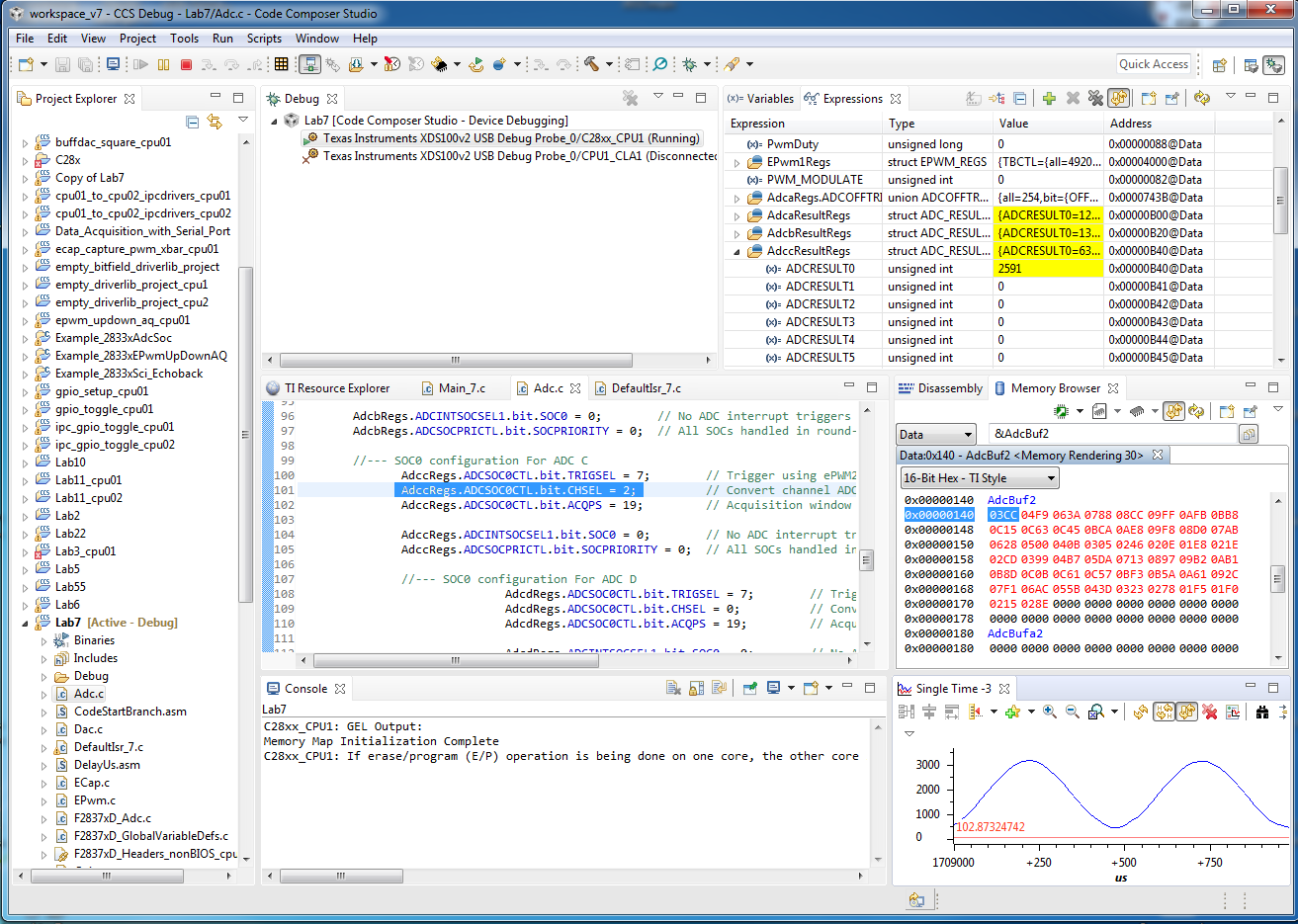
    have a look at the ccs window below where I'm savaing the ADCRESULT0 in AdcBuf2 and I show it in the Single Time 3 Graph ( the Sine Wave gragh is the Digital output of a sine input to ADCC2 which converted in to RESULT0 Bit). 

    I really appreciate your about it, is this correct operation? 

    Regards

    Hayder

  • Ken,

    I'm using F28379D  Experimenter Kit (controlCARD).  I tried both internal generated 2kHz PWM and sine wave as well as an external generated sine wave with 2kHz frequency.  I double checked that the correct input pin is being used. I'm using the attached file "TMDSCNCD28377D_180cCARD_pinout_R1_3.pdf" for pin selection.4162.TMDSCNCD28377D_180cCARD_pinout_R1_3.pdf

  • Hayder,

    Could you please try commenting out ADCA, ADCB, and ADCD and check if ADCC works properly?

    - Ken
  • Hi Ken, 

    I commented out  ADCA, ADCB, and ADCD and I tried the flowing thing: 

    1 -  This case ADCC0 didn't work, I connected input to pin 25 on the experimenter kit, look at the code in ADC.C and ISR. In the expression window, I didn't see any changes in the "AdccResultRegs".

    //--- SOC0 configuration For ADC C
    AdccRegs.ADCSOC0CTL.bit.TRIGSEL = 7;                    // Trigger using ePWM2-ADCSOCA
    AdccRegs.ADCSOC0CTL.bit.CHSEL = 0;                       // Convert channel ADCINC0 (Ch. 0)
    AdccRegs.ADCSOC0CTL.bit.ACQPS = 19;                     // Acquisition window set to (19+1)=20 cycles (100 ns with 200 MHz SYSCLK)

    AdccRegs.ADCINTSOCSEL1.bit.SOC0 = 0;                    // No ADC interrupt triggers SOC0 (TRIGSEL field determines trigger)
    AdccRegs.ADCSOCPRICTL.bit.SOCPRIORITY = 0;        // All SOCs handled in round-robin mode

    interrupt void ADCC1_ISR(void) // PIE1.3 @ 0x000D44 ADC-C interrupt #1
    {

    static Uint16 *AdcBufPtr2 = AdcBuf2; // Pointer to buffer

    PieCtrlRegs.PIEACK.all = PIEACK_GROUP1; // Must acknowledge the PIE group

    //--- Manage the ADC registers
    AdccRegs.ADCINTFLGCLR.bit.ADCINT1 = 1; // Clear ADCINT1 flag

    //--- Read the ADC result
    *AdcBufPtr2++ = AdccResultRegs.ADCRESULT0; // Read the result

    //--- Brute-force the circular buffer
    if( AdcBufPtr2 == (AdcBuf2 + ADC_BUF_LEN) )
    {
    AdcBufPtr2 = AdcBuf2; // Rewind the pointer to beginning
    }
    }

    2- This case ADCC1 didn't work, I connected input to pin 27 on the experimenter kit, look at the code in ADC.C and ISR. In the expression window, I didn't see any changes in the "AdccResultRegs"

    //--- SOC1 configuration For ADC C1
    AdccRegs.ADCSOC1CTL.bit.TRIGSEL = 7;                           // Trigger using ePWM2-ADCSOCA
    AdccRegs.ADCSOC1CTL.bit.CHSEL = 1;                              // Convert channel ADCINC1 (Ch. 1)
    AdccRegs.ADCSOC1CTL.bit.ACQPS = 19;                           // Acquisition window set to (19+1)=20 cycles (100 ns with 200 MHz SYSCLK)

    AdccRegs.ADCINTSOCSEL1.bit.SOC1 = 0;                           // No ADC interrupt triggers SOC0 (TRIGSEL field determines trigger)
    AdccRegs.ADCSOCPRICTL.bit.SOCPRIORITY = 0;              // All SOCs handled in round-robin mode

    interrupt void ADCC1_ISR(void) // PIE1.3 @ 0x000D44 ADC-C interrupt #1
    {

    static Uint16 *AdcBufPtr2 = AdcBuf2; // Pointer to buffer

    PieCtrlRegs.PIEACK.all = PIEACK_GROUP1; // Must acknowledge the PIE group

    //--- Manage the ADC registers
    AdccRegs.ADCINTFLGCLR.bit.ADCINT1 = 1; // Clear ADCINT1 flag

    //--- Read the ADC result
    *AdcBufPtr2++ = AdccResultRegs.ADCRESULT1; // Read the result

    //--- Brute-force the circular buffer
    if( AdcBufPtr2 == (AdcBuf2 + ADC_BUF_LEN) )
    {
    AdcBufPtr2 = AdcBuf2; // Rewind the pointer to beginning
    }
    }

    3- This case ADCC2 works, I connected input to pin 31 on the experimenter kit, look at the code in ADC.C and ISR below. In the expression window, I see there are change in the "AdccResultRegs" bit ADCRESULT2 which equivalent to the conversion.

    however, in this case the ISR AdcBuf2 array does not show anything and when I open the AdcBuf2 created to buffer the result of the AdcC2 there is now changes and the AdcBuf2 stays zero and don't update with the conversion of ADCRESULT2.

    //--- SOC2 configuration For ADC C2
    AdccRegs.ADCSOC2CTL.bit.TRIGSEL = 7;                                    // Trigger using ePWM2-ADCSOCA
    AdccRegs.ADCSOC2CTL.bit.CHSEL = 2;                                       // Convert channel ADCINC2 (Ch. 2)
    AdccRegs.ADCSOC2CTL.bit.ACQPS = 19;                                    // Acquisition window set to (19+1)=20 cycles (100 ns with 200 MHz SYSCLK)

    AdccRegs.ADCINTSOCSEL1.bit.SOC2 = 0;                                    // No ADC interrupt triggers SOC0 (TRIGSEL field determines trigger)
    AdccRegs.ADCSOCPRICTL.bit.SOCPRIORITY = 0;                       // All SOCs handled in round-robin mode

    interrupt void ADCC1_ISR(void) // PIE1.3 @ 0x000D44 ADC-C interrupt #1
    {

    static Uint16 *AdcBufPtr2 = AdcBuf2; // Pointer to buffer

    PieCtrlRegs.PIEACK.all = PIEACK_GROUP1; // Must acknowledge the PIE group

    //--- Manage the ADC registers
    AdccRegs.ADCINTFLGCLR.bit.ADCINT1 = 1; // Clear ADCINT1 flag

    //--- Read the ADC result
    *AdcBufPtr2++ = AdccResultRegs.ADCRESULT2; // Read the result

    //--- Brute-force the circular buffer
    if( AdcBufPtr2 == (AdcBuf2 + ADC_BUF_LEN) )
    {
    AdcBufPtr2 = AdcBuf2; // Rewind the pointer to beginning
    }
    }


    4- I this Case I repeated 3 but I changed the SOC from 2 to 0 as in the Code below from Adc.c and ISR file. In this case I see the conversion of ADCC2 in RESULT0 in the expression window  and I can see the Buffered results in the AdcBuf2 in  the memory browser as well. 

    //--- SOC0 configuration For ADC C2
    AdccRegs.ADCSOC0CTL.bit.TRIGSEL = 7;                                    // Trigger using ePWM2-ADCSOCA
    AdccRegs.ADCSOC0CTL.bit.CHSEL = 2;                                       // Convert channel ADCINC2 (Ch. 2)
    AdccRegs.ADCSOC0CTL.bit.ACQPS = 19;                                    // Acquisition window set to (19+1)=20 cycles (100 ns with 200 MHz SYSCLK)

    AdccRegs.ADCINTSOCSEL1.bit.SOC0 = 0;                                    // No ADC interrupt triggers SOC0 (TRIGSEL field determines trigger)
    AdccRegs.ADCSOCPRICTL.bit.SOCPRIORITY = 0;                       // All SOCs handled in round-robin mode

    interrupt void ADCC1_ISR(void) // PIE1.3 @ 0x000D44 ADC-C interrupt #1
    {

    static Uint16 *AdcBufPtr2 = AdcBuf2; // Pointer to buffer

    PieCtrlRegs.PIEACK.all = PIEACK_GROUP1; // Must acknowledge the PIE group

    //--- Manage the ADC registers
    AdccRegs.ADCINTFLGCLR.bit.ADCINT1 = 1; // Clear ADCINT1 flag

    //--- Read the ADC result
    *AdcBufPtr2++ = AdccResultRegs.ADCRESULT0; // Read the result

    //--- Brute-force the circular buffer
    if( AdcBufPtr2 == (AdcBuf2 + ADC_BUF_LEN) )
    {
    AdcBufPtr2 = AdcBuf2; // Rewind the pointer to beginning
    }
    }

    Honestly, I don't understand why the AdcBuf2 in  Case4 work but in Case 3 Doesn't work. 
    Any advice or I it's fine if I keep with using Case 4

    Kind Regards 

    Hayder 

  • Hayder,

    Please see the F28379D data sheet at:

    www.ti.com/lit/sprs880.pdf

    On page 96 note that for ADC-C channels C0 and C1 are not pinned out. ADC-C only has channels C2, C3, C4, and C5 pinned out.

    I hope this helps. If this answers your question, please click the green "Verified Answer" button. Thanks.

    - Ken
  • Hi Ken, 

    Thanks a lot for the clarification.
    I still don't understand on thing, why when I use SOC2 with ADCC channel 2, The ISR AdcBuf2  doesn't work as in case 3 in my previous comment while when I use SOC0 and RESULT0, The AdcBuf2 shows the buffered conversion as in  case 4. 

    Kind Regards

    Hayder

  • Hayder,

    From what you described, for both case 3 and 4 the ADC is working as expected, with SOC2 and SOC0. It is just case 3 where you are having problems with the buffer in the ISR. Please double check the ISR (breakpoints, single-step, etc.).

    - Ken
  • Hi Ken,

    I tried the ISR (breakpoints, single-step) and I didn't see any difference. however it's not that important at the moment as the ADCC2 with soc0 is working probably and the other ADC work probably.

    Thanks for your help
    Regards
    Hayder