This thread has been locked.

If you have a related question, please click the "Ask a related question" button in the top right corner. The newly created question will be automatically linked to this question.

TMS320F28069: I2C Communiciation with MCP9808

Part Number: TMS320F28069
Other Parts Discussed in Thread: C2000WARE

Hi,

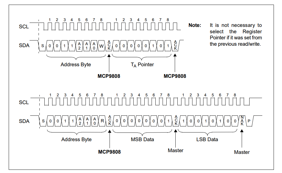
I am trying to read temperature data from MCP9808 via I2C of F28069 MCU. But I could not. Please find the code below. Do you have any suggestion?

MCP9808

// I2C GPIO Configuration
/* Enable internal pull-up for the selected pins */
GpioCtrlRegs.GPBPUD.bit.GPIO32 = 0;    // Enable pull-up for GPIO32 (SDAA)
GpioCtrlRegs.GPBPUD.bit.GPIO33 = 0;    // Enable pull-up for GPIO33 (SCLA)
/* Set qualification for selected pins to asynch only */
GpioCtrlRegs.GPBQSEL1.bit.GPIO32 = 3;  // Asynch input GPIO32 (SDAA)
GpioCtrlRegs.GPBQSEL1.bit.GPIO33 = 3;  // Asynch input GPIO33 (SCLA)
/* Configure I2C pins using GPIO regs*/
GpioCtrlRegs.GPBMUX1.bit.GPIO32 = 1;   // Configure GPIO32 for SDAA operation
GpioCtrlRegs.GPBMUX1.bit.GPIO33 = 1;   // Configure GPIO33 for SCLA operation
void InitI2C()
{
   // Initialize I2C

	I2caRegs.I2CMDR.bit.IRS = 0;
	I2caRegs.I2CPSC.all = 8;		// Prescaler - need 7-12 Mhz on module clk
	I2caRegs.I2CCLKL = 10;			// NOTE: must be non zero
	I2caRegs.I2CCLKH = 5;			// NOTE: must be non zero
	I2caRegs.I2CIER.all = 0x24;		// Enable SCD & ARDY interrupts

	I2caRegs.I2CMDR.all = 0x0020;	// Take I2C out of reset
					// Stop I2C when suspended

	I2caRegs.I2CFFTX.all = 0x6000;	// Enable FIFO mode and TXFIFO
	I2caRegs.I2CFFRX.all = 0x2040;	// Enable RXFIFO, clear RXFFINT,

	return;
}
long GetTemperature(void)
{
	long Temperature;
	long TempUpperByte;
	long TempLowerByte;

	I2caRegs.I2CMDR.bit.IRS = 1;                // reset I2C

	// Make sure I2C is not busy and has stopped
	while (I2caRegs.I2CSTR.bit.BB == 1);        // busy loop
	I2caRegs.I2CSTR.bit.SCD = 1;                // Clear the SCD bit (stop condition bit)
	while(I2caRegs.I2CMDR.bit.STP == 1);        // stop bit loop

	//I2caRegs.I2CMDR.all = 0x6620;                 // start, stop, no rm, reset i2c  01101110 00100000
	I2caRegs.I2CMDR.bit.NACKMOD = 0;            // NACK mode bit
	I2caRegs.I2CMDR.bit.FREE = 1;               // Run free I2C when suspended
	I2caRegs.I2CMDR.bit.STT = 1;                // START condition bit
	I2caRegs.I2CMDR.bit.STP = 0;                // STOP condition bit
	I2caRegs.I2CMDR.bit.MST = 1;                // Master mode
	I2caRegs.I2CMDR.bit.TRX = 1;                // Transmitter mode
	I2caRegs.I2CMDR.bit.XA = 0;                 // 7-bit addressing mode
	I2caRegs.I2CMDR.bit.RM = 0;                 // Nonrepeat mode
	I2caRegs.I2CMDR.bit.DLB = 0;                // Digital loopback mode is disabled
	I2caRegs.I2CMDR.bit.IRS = 1;                // The I2C module is enabled
	I2caRegs.I2CMDR.bit.STB = 0;                // The I2C module is not in the START byte mode
	I2caRegs.I2CMDR.bit.FDF = 1;                // Free data format mode is disabled
	I2caRegs.I2CMDR.bit.BC = 0;                 // 8 bits per data byte

	while(I2caRegs.I2CSTR.bit.XRDY == 0);       // Do nothing till bus is free
	I2caRegs.I2CMDR.bit.STT = 1;                // START condition bit
	I2caRegs.I2CDXR = 0x32;
	while(I2caRegs.I2CSTR.bit.NACK == 1);
	I2caRegs.I2CDXR = 0x05;                      // register address of the sensor (1 byte)
	while(I2caRegs.I2CSTR.bit.NACK == 1);
	I2caRegs.I2CMDR.bit.STT = 1;                // START condition bit
	I2caRegs.I2CDXR = 0x33;
	while(I2caRegs.I2CSTR.bit.NACK == 1);
	TempUpperByte = I2caRegs.I2CDRR;
	while(I2caRegs.I2CSTR.bit.NACK == 1);
	I2caRegs.I2CMDR.bit.NACKMOD == 1;
	TempLowerByte = I2caRegs.I2CDRR;
	while(I2caRegs.I2CSTR.bit.NACK == 0);
	I2caRegs.I2CMDR.bit.STP = 1;

	Temperature = (TempUpperByte * 16 + TempLowerByte / 16);

	return Temperature;
}

  • Mert,

    Please expand on what specific issue you are facing. The I2C can be a tricky module, and it is best to be clear about what you are stuck on.

    We do not supply driver code for external devices, though C2000Ware has an EEPROM example as well as our I2C bootloader source. Have you taken a look at those?

    Thanks
    Mark
  • Mark,

    Thank you for your comment. I have looked EEPROM example, but code is different from what I need. I can understand that do not supply driver code for external devices, but problem is I2C example and explanations is not enough for my needs. Do you have any simple read and wirte library for general purpose?

    I am trying to get write and read sequence for given I2C message figure with code I shared. I am not sure the written code will do this sequence for communication. Maybe I am doing something wrong. Could I send just only address with read bit without Free Data Format bit set? 

    Could you please examine code and comment for is it OK for the given I2C messaging sequence figure?

    Thank you, 

  • Mert,

    The EEPROM and bootROM code is the most generic code that we have at this time.

    Is the code not working for you? How is it not working? Have you observed the signals on a scope?

    Briefly looking at your code, it see that you set the Start condition during your configuration phase of GetTemperature() and then proceed to do more configuration.

    I also think your polling of the NACK bit is backwards in your data receive phase. NACK = 0 means that a ACK was received, NACK = 1 means a NACK was received.

    You also never set up the I2C to know how many bytes it should expect to receive.
    Check out the I2C_Boot.c file and the I2C_GetWord function of the I2C boot source: ..\C2000Ware_<version>libraries\boot_rom\f2806x\v1_1\rom_sources\source
    This function appears to match exactly what the receive portion of your temp sensor expects.

    I hope this gets you moving.

    Thanks,
    Mark
  • Hi Mark,

    Thank you for you support. I can understand the problems. My mistakes and suggestions is listed below for records.

    • I2C_Boot.c file is more clear than other EEPROM example code. If you had not pointed that file I could not find this example and could not understand. It should have better accessiblity from documents.
    • My main problem is shifting slave address for Read and Write sequence. The real slave address should be used for I2CSAR register, Read and Write bit implementation done by MCU. But it is not clear in the document.
    • The other mistake was made in parsing bytes from sensor. But it is not related with TI.

    Best Regards,