This thread has been locked.

If you have a related question, please click the "Ask a related question" button in the top right corner. The newly created question will be automatically linked to this question.

CCS/LAUNCHXL-F28069M: InitFlash(). Blinky Led Program Stucked because InitFlash()

Part Number: LAUNCHXL-F28069M
Other Parts Discussed in Thread: CONTROLSUITE

Tool/software: Code Composer Studio

Hi everyone! This is Mike.

First of all I wanna thank those who help in this forum.

Now, After been trying for while I didn't get to program my LAUNCHXL-F28069M onto the Flash, here is the code. If I eliminate the InitFlash(); instruction my program works properly, but when I insert that instruction my firmware just doesn't work.

Any Suggestions?

I've been reading about Reset CPU and then Run again, It doesn't work to me. I have read Running_From_Flash_spra958l.pdf And  I think something I'm doing wrong .
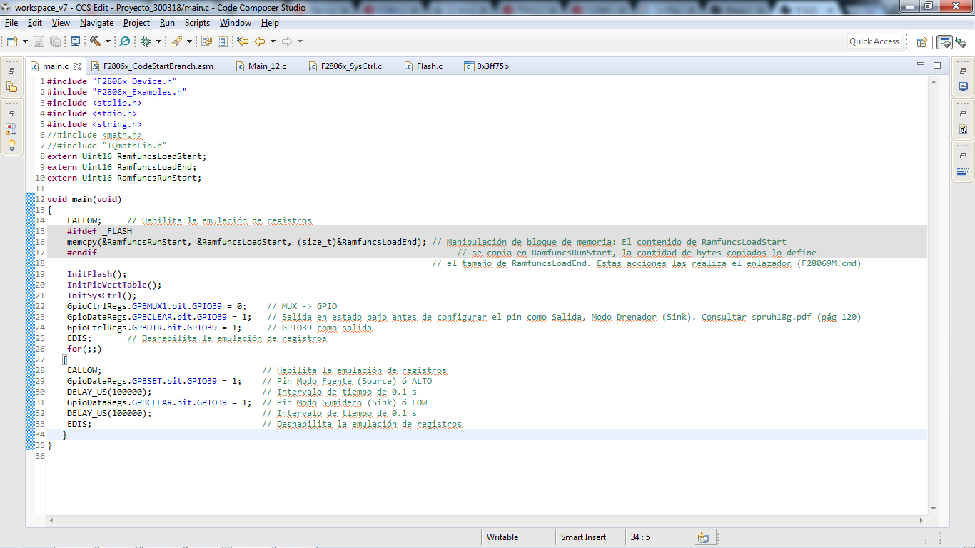
Please Somebody tell how to deal with this.

Regards.

Mike

  • Is Anybody out there ?
    LAUNCHXL-F28069M
  • Hi Mike,

    InitFlash() needs few routines to be executed from RAM. The RAM routines have to be copied from Flash. This is done as part of ' memcpy(&RamfuncsRunStart, &RamfuncsLoadStart, (size_t)&RamfuncsLoadSize);'. As this part of the code is not executed in your code there is an issue in your code. Please define _FLASH in the CCS project properties -> 'Predefined Symbols'.

    To program onto flash please use 'CPU1_FLASH' build configuration. It takes care of adding the define '_FLASH'.

    You can change the configuration from Right Click on the project in CCS window -> Build Configurations -> Set Active -> Select 'CPU1_FLASH'.

    Please let us know if there is an issue.

    Thanks,

    Katta

  • Thanks Katta 

    I tried to do what you said, The definition "_FLASH" was ok, but the second step you said I couldn't do it. Look at the photo, you will see that "CPU1_FLASH" It's not an option.  Just there are two  -> DEBUG, ->RELEASE.

    Any Suggestions ?

    Regards 

    Mike

  • Hi Mike,

    Ok. It looks like you have created own project from blink led project.
    Then adding just the definition should be fine. Are you using a FLASH linker command file? It will be present in the same location as the F28004x RAM linker command file.

    Please let me know.

    Thanks,
    Katta
  • Hi Katta
    The project I did it myself based on the lectures I've done about registers. I put the F28069M.cmd linker and I have discovered something. I moved the EALLOW instruction under of Initflash(); And It worked, Also I've noticed this not will work until I change the ADCSOC0 to ADCSOC1. How to get the program in Flash? Why did not work the program with ADCSOC0 ?

    Regards

    Mike

  • Hi Mike,

    Please run any existing project on Flash from the controlsuite on the board.
    Then you can compare with your project one by one to see if there is a step you are missing.

    Please refer to the following links for your reference:

    Running an Application from Internal Flash Memory on the TMS320F28xx DSP (www-s.ti.com/.../spra958)

    Copying Compiler Sections from Flash to RAM on the TMS320F28xxx DSCs (www-s.ti.com/.../spraau8)

    Regarding ADCSOC0 refer to an example on ADC.

    Meanwhile it is would be better to attach your project so that we can look at your project and to check for any incorrect configuration.

    Thanks,
    Katta

  • I missed to put my new code hehe

    Here it is

     It´s working now, but I'm not getting to put my code in the Flash, Thanks anyway.

    If you see something wrong, please tell me.

    Thanks

    Regards

    Mike

    #include "F2806x_Device.h"
    #include "F2806x_Examples.h"
    #include "DSP28x_Project.h"
    #include <stdlib.h>
    #include <stdio.h>
    #include <string.h>
    #include <math.h>
    #include "IQmathLib.h"
    
    extern Uint16 RamfuncsLoadStart;
    extern Uint16 RamfuncsLoadEnd;
    extern Uint16 RamfuncsRunStart;
    __interrupt void adc_isr(void);
    
    
    /* Declaración de variables Globales*/
    
    Uint16 ADC_Buffer[154];
    Uint32 ADC_Buffer2[154];
    _iq ADC_Buffer3;
    Uint32 ADC_Buf_Sum;
    _iq ADC_Buffer4;
    _iq RMS;
    float DC;
    Uint16 conv;
    Uint16 cont;
    Uint16 i;
    
    
    void main(void)
    {
    
    
        memcpy(&RamfuncsRunStart, &RamfuncsLoadStart, (size_t)&RamfuncsLoadEnd); // Manipulación de bloque de memoria: El contenido de RamfuncsLoadStart
                                                                                 // se copia en RamfuncsRunStart, la cantidad de bytes copiados lo define
                                                                                 // el tamaño de RamfuncsLoadEnd. Estas acciones las realiza el enlazador (F28069M.cmd)
        InitFlash();   // Inicializa las funciones para copiar el programa a la memoria Flash
        InitSysCtrl(); // Inicializa el Sistema de Control: PLL, WD, Peripheral Clocks.
        DINT;          // Deshabilita las interrupciones del CPU
        InitPieCtrl(); // Inicializa los registros de control del Puerto de Interrupciones Expandido a sus estado predeterminado
        IER = 0X0000;  // Deshabiita las interrupciones del CPU
        IFR = 0X0000;  // Limpia las banderas de interrupción del CPU
        InitPieVectTable(); //Inicializa la tabla de arreglos de interrupción, las interrupciones utilizadas son remapeadas en esta función
        EALLOW;             // Habilita la emulación de registros
        PieVectTable.ADCINT1 = &adc_isr; // El contenido del subprograma de interrupción "adc_isr" es copiado por el subprograma de interrupción "ADCINT1" contenido en la tabla.
        EDIS;                            // Deshabilita la emulación de registros
        InitAdc();                       // Inicializa el módulo del ADC
        AdcOffsetSelfCal();              // Ajuste de offset del ADC debido a su construcción
        PieCtrlRegs.PIEIER1.bit.INTx1 = 1;// Habilita la Interrupción 1.1 en el Puerto de expansión de interrupciones
        IER |= M_INT1;                   // Habilita la interrupción 1 del CPU
        EINT;                            // Habilita las interrupciones globales
        ERTM;                            // Habilita las interrupciones en tiempo real
        conv=0;                          // Variable auxiliar que define, temporalmente, la longitud del Buffer
        //ADC_Buffer2=0;
        EALLOW;                          // Habilita la emulación de registros
        AdcRegs.ADCCTL2.bit.ADCNONOVERLAP = 1; // Habilita el modo de sobrelapamiento de muestras
        AdcRegs.ADCCTL1.bit.INTPULSEPOS = 1;   // Control de pulso generador de interrupción -> 0 = Inicio de conversión, 1 = Un ciclo por resultado
        AdcRegs.INTSEL1N2.bit.INT1E = 1;       // Habilita ADCINT1
        AdcRegs.INTSEL1N2.bit.INT1CONT = 0;    // Modo de interrupciones continuas deshabilitado -> 0= Pulso generado si la bandera es limpiada por SW, 1=Pulso generado cada EOC
        AdcRegs.INTSEL1N2.bit.INT1SEL = 1;     // Final de conversion 1 (EOC 1) es el disparo (trigger) de ADCINT1
        AdcRegs.ADCSOC1CTL.bit.CHSEL = 1;      // Inicio de conversión 0 (SOC) para el canal ADCIN1 (pin 29)
        AdcRegs.ADCSOC1CTL.bit.TRIGSEL = 5;    // ePWM 1 es el disparo para SOC1
        AdcRegs.ADCSOC1CTL.bit.ACQPS = 6;      // Ventana de Sample/Holding a 7 ciclos del reloj del ADC
        EPwm1Regs.ETSEL.bit.SOCAEN = 1;        // Selección de registros para Eventos de Disparo -> Disparos en SOC A habilitados
        EPwm1Regs.ETSEL.bit.SOCASEL = 4;       // Selección de SOC en la comparación del contador ascente de A
        EPwm1Regs.ETPS.bit.SOCAPRD = 1;        // Generación de SOC al primer evento
        EPwm1Regs.CMPA.half.CMPA = 0x0080;     // Valor decimal: 128. Para un Duty Cycle en modo de conteo ascendente del 99% -> CMPA = (100% - Duty Cycle) * (TBPRD + 1) - 1
        EPwm1Regs.TBPRD = 0xFFFF;              // Valor decimal: 65535. Periodo de conteo en modo ascendente
        EPwm1Regs.TBCTL.bit.CTRMODE = 0;       // Mode conteo ascendente
        GpioCtrlRegs.GPBMUX1.bit.GPIO39 = 0;   // MUX -> GPIO
        GpioDataRegs.GPBCLEAR.bit.GPIO39 = 1;  // Salida en estado bajo antes de configurar el pin como Salida, Modo Drenador (Sink). Consultar spruh18g.pdf (pág 120)
        GpioCtrlRegs.GPBDIR.bit.GPIO39 = 1;    // GPIO39 como salida
        EDIS;                                  // Deshabilita la emulación de registros
        for(i=0;i<154;i++)
        {
            ADC_Buffer[i]=0;
        }
        for(i=0;i<154;i++)
          {
              ADC_Buffer2[i]=0;
          }
        for(;;)
       { // Inicio de For
            EALLOW;                                // Habilita la emulación de registros
            GpioDataRegs.GPBSET.bit.GPIO39 = 1;    // Pin Modo Fuente (Source) ó ALTO
            DELAY_US(100000);                      // Intervalo de tiempo de 0.1 s
            GpioDataRegs.GPBCLEAR.bit.GPIO39 = 1;  // Pin Modo Sumidero (Sink) ó LOW
            DELAY_US(100000);                      // Intervalo de tiempo de 0.1 s
            EDIS;                                  // Deshabilita la emulación de registros
       } // Fin de for
    
    } // Fin de programa principal
    
    __interrupt void
    adc_isr(void) // Inicio del programa de interrupción
    {
    
        ADC_Buffer[conv] = AdcResult.ADCRESULT1;   // Cada espacio o localidad del arreglo es llenado con el resultado del registro AdcResult
        ADC_Buffer2[conv] = _IQmpy(_IQ(ADC_Buffer[conv]),_IQ(ADC_Buffer[conv])); /* VRMS */
        ADC_Buf_Sum += ADC_Buffer2[conv];
        //ADC_Buffer2 += ADC_Buffer[conv]; /* VDC */
    
        if (conv == 153)                           // La variable conv si es igual a la longitud del buffer menos uno entonces se reinicia
        {
            ADC_Buffer3 = _IQdiv(_IQ(ADC_Buf_Sum),_IQ(conv+1));
            //DC=(3.3*ADC_Buffer3)/4096;  /* VDC */
            ADC_Buffer4 = _IQsqrt(ADC_Buffer3);  /* VRMS */
            RMS=_IQmpy(_IQ(ADC_Buffer4),_IQ(3.3/4096));      /* VRMS */
            conv = 0;
            ADC_Buf_Sum =0;
            for(i=0;i<154;i++)
            {
                ADC_Buffer[i]=0;
            }
            for(i=0;i<154;i++)
              {
                  ADC_Buffer2[i]=0;
              }
        }
    
        else                                      // Si la variable conv no es igual a la longitud del buffer menos uno entonces incrementa en uno
        {
            conv++;
        }
        AdcRegs.ADCINTFLGCLR.bit.ADCINT1 = 1;     // Limpia la bandera de interrupción del ADC
        PieCtrlRegs.PIEACK.all = PIEACK_GROUP1;   // El bloque de expandido de interrupción de perifericos reconoce una interrupción en el grupo 1
        //return;
    
    } // Fin del subprgrama de interrupción
    

  • Mike,

    For reference, you might want to review the following F28069 workshop at:

    processors.wiki.ti.com/.../C2000_Archived_Workshops

    See lab 12 exercise for the flash details and lab 6 exercise for the ADC.

    I hope this helps. If this answers your question, please click the green "Verified Answer" button. Thanks.

    - Ken
  • Hi Katta

    Can you see something wrong with this code?

    Regards
    Mike
  • Hi Mike,

    I will check with ADC expert. Please give additonal time. Meanwhile did you check the lab 6 exercise for the ADC?

    Thanks,
    Katta
  • Hi Katta

    I checked the Lab 6 and I did not see anything wrong with the code, but I missed some register about the sample mode. Do you think it will be the problem ?

    Regards
    Mike
  • Hi katta
    I I passed through this issue getting the ADC in the way it has to be at exercise 6. The time it took was not productive so I just put hand on other parts of the firmware.
    Thanks
    Mike