This thread has been locked.

If you have a related question, please click the "Ask a related question" button in the top right corner. The newly created question will be automatically linked to this question.

CCS/TMS320F28377S: TMS320F28377S

Part Number: TMS320F28377S

Tool/software: Code Composer Studio

I WANNA TO GENERATE A ABNORMAL PWM WAVEFORM, AS SWITCH Sb SHOWS IN WORD, PLEASE GIVE ME SOME TIPS OR GUIDE. THANKS WAVEFORM.docx

  • Wentao,

    Here are some questions for you to answer:

    1. Is there a relationship between Sa, Sb and Sc? You need to generate only Sb?
    2. What are the values for T0, T1, T2 and T7?

  • Yes, there is a relationship among the three switches, that is I know the accurate time point of the Sb rising edges and falling edges. And the values for t0 t1 t2 are also known.So I wanna to generate waveform Sb. but the question is I don't know how to generate such wave in ePWM modules,  because CMPA and CMPB are not enough seemingly.

  • You are correct from my understanding, You cannot just set up the CMPA and CMPB and expect the ePWM module to generate the signal needed. But here is how I would generate this signal.

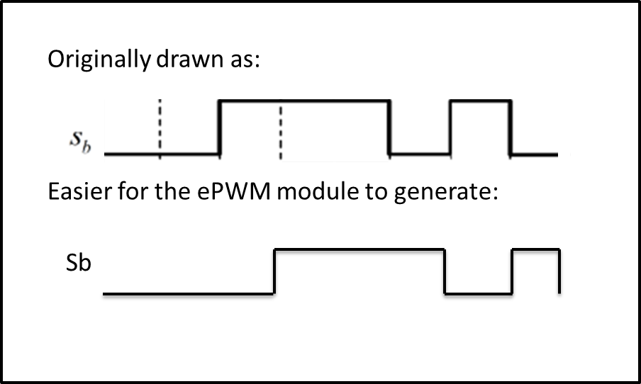
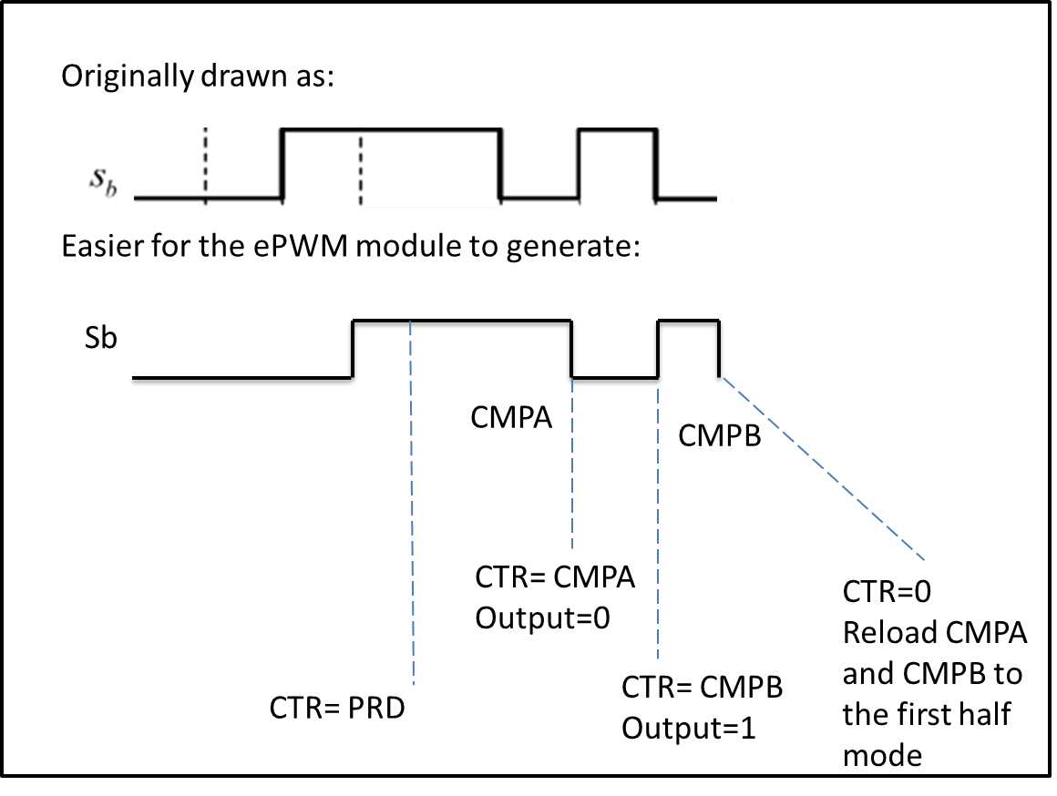
    First I would Think of the signal in a different way.

    Basically I would just shift the signal to the right by T0/2.

    Now I would do the following to generate the signal:

    Set the ePWM to up/down mode with shaddow load on boath CTR=0 and CTR=PRD.

    For the first half of the signal do, 

    For the second half,

  • thanks for your answer. your implementation way inspires me and i have some small QUESTIONs in this approach :
    1. is it reasonable and feasible that in the program, the cmpa and cmpb are changed or loaded in pwm interrupt when ctr equals 0 or prd?
    2. without setup in AQCTL , at the end of the sb signal in your way, when ctr=0, the sb signal would not become low and it remains high until ctr reaches cmpa after prd. so this way may not feasible .
    LOOKING FORWARD YOUR REPLY.
    THANKS SINCERELY
  • 1. Since the CMPA and CMPB are being changed in the interrupts, it is important to note that you must be using shadow mode and changing the values one event before you need them to take effect.
    2. I would also use the AQ module in shaddow mode and configure it to clear the output low on CTR=0.
  • Successfully the signal Sb was generated with your help. But here, the signal is not independent of Sa and Sc, for the high or low level of switches signals at the same moment can compose space vector in SVPWM technique. Actually, this abnormal signal wave comes from an novel SVPWM according to a published paper.

    so, shifting the signal Sb would generate another voltage vector 010 during the last time period 2/T0 when Sa=0,Sb=1,Sc=0, but the original three signals Sa, Sb, Sc only have four states- 000 100 110 111 110 100 000, if we define high means 1, low means 0.

    thus, shifting three signals may be needed. 

    without shifting, is there any way to generate the three signals?

    thanksmodified svpwm.pdf

  • I just went through the documentation to see if we could use CMPC and CMPD to help but unfortunately I don't think that possible. Shifting is the only solution I can come up with at the moment. This is a very interesting signal.

  • hello, do you think it is feasible that the three edges after PRD can be done by changing CMPA and CMPB in immediate mode not shadow mode?

  • So you could set up CMPA and B before period for the first half
    Then CMPA and CMPB after the period for the second half
    Then have a CMPC interrupt occur before the extra change in state which we are not shifting anymore, change CMPA in that interrupt

    I do think this would work even though I have never seen anyone try it. One thing that comes into play is how fast the PWM clock is, to change the CMPA,B in interrupts, the cycles that it takes to enter an interrupt must be considered.
  • yes,when the falling edges come in the second half of the PWM period , I use CMPC interrupt where epwm is forced low and set up new cmpa and cmpb in immediate mode. so the signal can be generated. here comes another problem:
    when the counter equals the cmpc, one epwm module interrupt 2 happens. and another epwm interrupt 1 happens when the counter equals zero where the cmpa is set up in the first half of the period. thus we must make sure that the two counters have the same value at every moment. is it correct? and do you have some ideas to make sure it? thanks
  • I am not sure exactly what you mean. But you can always check the cmp values after you write, to make sure they are correct.