Tool/software: Code Composer Studio
Hi,
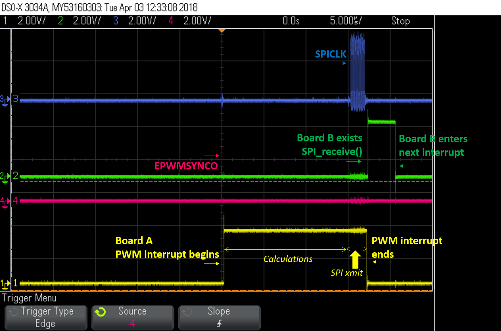
I have two TMS320C2000 Experimenter Kits with 28335, and let's call them A and B. Synchronized 7kHz PWM interrupt are applied on both board by using EPWMSYNCO I/O, and it works well.
After A board enters PWM interrupt, it will send 16bit data by SPI (baud rate: 9.375MHz) after finishing some calculation. FYI, the time taking for the calculation before SPI transmission is about 30us.
For B board, it waits for the SPI data reception right after entering the PWM interrupt.
With 16 bit data transmission and synchronized 7kHz PWM interrupt, I believe the time for B board to receive the data from SPI in the PWM interrupt should be more than enough.
However, I find that B board takes the whole time of the interrupt to wait for the data. Here is the timing measured from the scope.
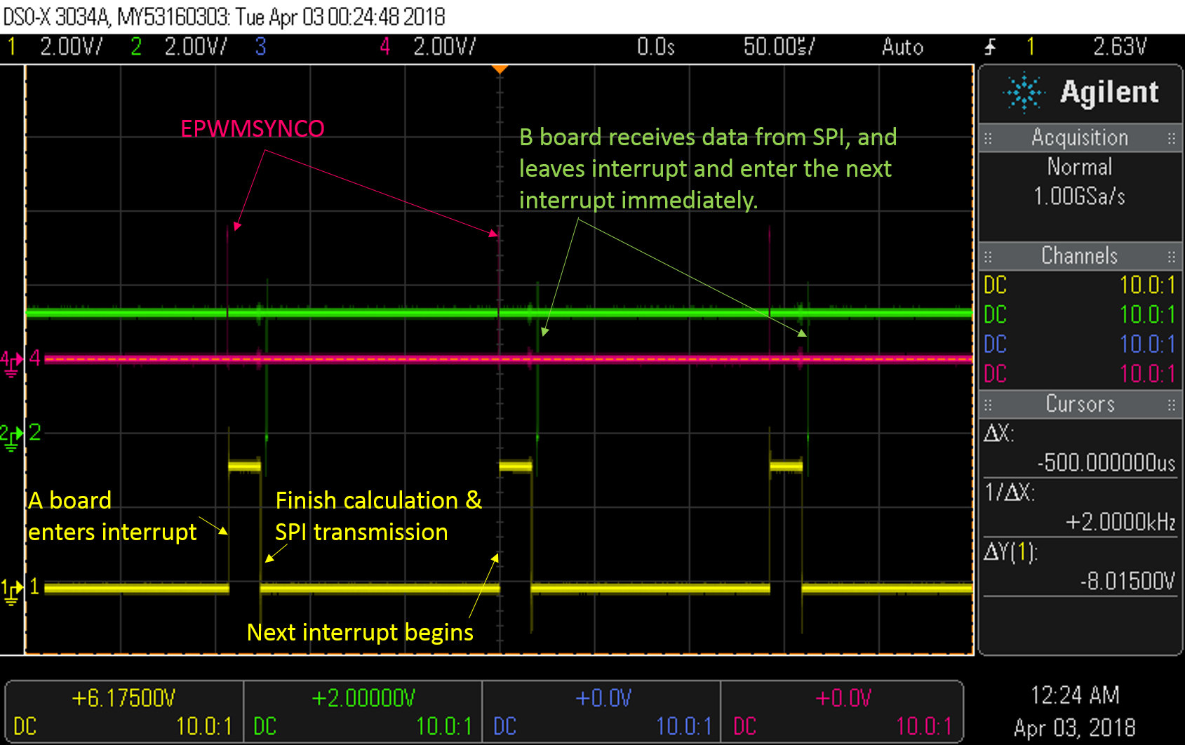
The data received by B board is also not complete. Some data points are missing.
The SPI setup is the following:
1) A board:
void spi_init()
{
SpiaRegs.SPICCR.bit.SPISWRESET = 0; // Clear this bit before changing SPI configuration
SpiaRegs.SPICCR.all = 0x000F; // Reset on, write:rising edge; read: falling edge
// no loop back, 16-bit char bits
// 0000 1111
SpiaRegs.SPICTL.all = 0x0006; // Enable master mode, normal phase (no delay half cycle),
// enable talk, and SPI int disabled.
// 0000 0110
SpiaRegs.SPIBRR = 0x0000; // LSPCLK/4, 37.5 MHz/4 = 9.375 MHz
SpiaRegs.SPICCR.all = 0x008F; // Relinquish SPI from Reset, 1100 1111
SpiaRegs.SPIPRI.bit.FREE = 1; // Set so breakpoints don't disturb xmission
}
void spi_xmit(Uint16 a)
{
volatile Uint16 dummy_x = 0;
GpioDataRegs.GPACLEAR.bit.GPIO19 = 1;
SpiaRegs.SPITXBUF=a;
while(SpiaRegs.SPISTS.bit.INT_FLAG == 0) { }
dummy_x = SpiaRegs.SPIRXBUF;
GpioDataRegs.GPASET.bit.GPIO19 = 1;
}
2) B board:
void spi_init()
{
SpiaRegs.SPICCR.bit.SPISWRESET = 0; // Clear this bit before changing SPI configuration
SpiaRegs.SPICCR.all = 0x000F; // Reset on, write:rising edge; read: falling edge
// no loop back, 16-bit char bits
// 0000 1111
SpiaRegs.SPICTL.all = 0x0002; // Enable slave mode, normal phase (no delay half cycle),
// enable talk, and SPI int disabled.
// 0000 0010
SpiaRegs.SPIBRR = 0x0000; // LSPCLK/4, 37.5 MHz/4 = 9.375 MHz
SpiaRegs.SPICCR.all = 0x008F; // Relinquish SPI from Reset, 1100 1111
SpiaRegs.SPIPRI.bit.FREE = 1; // Set so breakpoints don't disturb xmission
}
void spi_receive()
{
while(SpiaRegs.SPISTS.bit.INT_FLAG == 0) { }
Drive_data = SpiaRegs.SPIRXBUF;
}
Due to the application in my research, PWM interrupt is necessary, therefore the interrupt from SPI data reception is not considered here.
Does anyone have an idea for solving this issue? I appreciate any help from you.
Thanks. :)
Hung-Yen