This thread has been locked.

If you have a related question, please click the "Ask a related question" button in the top right corner. The newly created question will be automatically linked to this question.

CCS/TMS320F28335: Error connecting to the target, Device may be locked

Part Number: TMS320F28335

Tool/software: Code Composer Studio

Respected Sir,

                     I connected the probe ,after that I have tried the Target confign i.e.[probe=TI XDS100v2 USB Debug probe] and controller is TMS320F28335 is selected.But test connection is failed.Not able to dump the program.whilie dumping the program following message come,how to resolve the above problem.

Error msg as follows:

Error connecting to the target:
(Error -1015 @ 0x0)
Device is not responding to the request. Device may be locked, or the debug probe connection may be unreliable. Unlock the device if possible (e.g. use wait in reset mode, and power-cycle the board). If error persists, confirm configuration and/or try more reliable JTAG settings (e.g. lower TCLK).
(Emulation package 7.0.100.1)
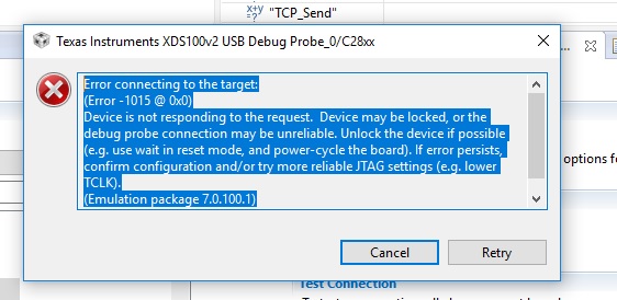
  • Hi Mahesh,

    Which is the target board? Launchpad/Controlcard or your custom board?

    Regards,
    Sudharsanan
  • I perform a JTAG integrity test? Its available in CCS -> Target Configuration -> Test Connection

    then following window will come:

    [Start: Texas Instruments XDS100v2 USB Debug Probe_0]

    Execute the command:

    %ccs_base%/common/uscif/dbgjtag -f %boarddatafile% -rv -o -F inform,logfile=yes -S pathlength -S integrity

    [Result]


    -----[Print the board config pathname(s)]------------------------------------

    C:\Users\wisdom\AppData\Local\TEXASI~1\CCS\
    ti\0\0\BrdDat\testBoard.dat

    -----[Print the reset-command software log-file]-----------------------------

    This utility has selected a 100- or 510-class product.
    This utility will load the adapter 'jioserdesusb.dll'.
    The library build date was 'Dec 11 2017'.
    The library build time was '12:04:14'.
    The library package version is '7.0.100.1'.
    The library component version is '35.35.0.0'.
    The controller does not use a programmable FPGA.
    The controller has a version number of '4' (0x00000004).
    The controller has an insertion length of '0' (0x00000000).
    This utility will attempt to reset the controller.
    This utility has successfully reset the controller.

    -----[Print the reset-command hardware log-file]-----------------------------

    The scan-path will be reset by toggling the JTAG TRST signal.
    The controller is the FTDI FT2232 with USB interface.
    The link from controller to target is direct (without cable).
    The software is configured for FTDI FT2232 features.
    The controller cannot monitor the value on the EMU[0] pin.
    The controller cannot monitor the value on the EMU[1] pin.
    The controller cannot control the timing on output pins.
    The controller cannot control the timing on input pins.
    The scan-path link-delay has been set to exactly '0' (0x0000).

    -----[The log-file for the JTAG TCLK output generated from the PLL]----------

    There is no hardware for programming the JTAG TCLK frequency.

    -----[Measure the source and frequency of the final JTAG TCLKR input]--------

    There is no hardware for measuring the JTAG TCLK frequency.

    -----[Perform the standard path-length test on the JTAG IR and DR]-----------

    This path-length test uses blocks of 64 32-bit words.

    The test for the JTAG IR instruction path-length failed.
    The JTAG IR instruction scan-path is stuck-at-ones.

    The test for the JTAG DR bypass path-length failed.
    The JTAG DR bypass scan-path is stuck-at-ones.

    -----[Perform the Integrity scan-test on the JTAG IR]------------------------

    This test will use blocks of 64 32-bit words.
    This test will be applied just once.

    Do a test using 0xFFFFFFFF.
    Scan tests: 1, skipped: 0, failed: 0
    Do a test using 0x00000000.
    Test 2 Word 0: scanned out 0x00000000 and scanned in 0xFFFFFFFF.
    Test 2 Word 1: scanned out 0x00000000 and scanned in 0xFFFFFFFF.
    Test 2 Word 2: scanned out 0x00000000 and scanned in 0xFFFFFFFF.
    Test 2 Word 3: scanned out 0x00000000 and scanned in 0xFFFFFFFF.
    Test 2 Word 4: scanned out 0x00000000 and scanned in 0xFFFFFFFF.
    Test 2 Word 5: scanned out 0x00000000 and scanned in 0xFFFFFFFF.
    Test 2 Word 6: scanned out 0x00000000 and scanned in 0xFFFFFFFF.
    Test 2 Word 7: scanned out 0x00000000 and scanned in 0xFFFFFFFF.
    The details of the first 8 errors have been provided.
    The utility will now report only the count of failed tests.
    Scan tests: 2, skipped: 0, failed: 1
    Do a test using 0xFE03E0E2.
    Scan tests: 3, skipped: 0, failed: 2
    Do a test using 0x01FC1F1D.
    Scan tests: 4, skipped: 0, failed: 3
    Do a test using 0x5533CCAA.
    Scan tests: 5, skipped: 0, failed: 4
    Do a test using 0xAACC3355.
    Scan tests: 6, skipped: 0, failed: 5
    Some of the values were corrupted - 83.3 percent.

    The JTAG IR Integrity scan-test has failed.

    -----[Perform the Integrity scan-test on the JTAG DR]------------------------

    This test will use blocks of 64 32-bit words.
    This test will be applied just once.

    Do a test using 0xFFFFFFFF.
    Scan tests: 1, skipped: 0, failed: 0
    Do a test using 0x00000000.
    Test 2 Word 0: scanned out 0x00000000 and scanned in 0xFFFFFFFF.
    Test 2 Word 1: scanned out 0x00000000 and scanned in 0xFFFFFFFF.
    Test 2 Word 2: scanned out 0x00000000 and scanned in 0xFFFFFFFF.
    Test 2 Word 3: scanned out 0x00000000 and scanned in 0xFFFFFFFF.
    Test 2 Word 4: scanned out 0x00000000 and scanned in 0xFFFFFFFF.
    Test 2 Word 5: scanned out 0x00000000 and scanned in 0xFFFFFFFF.
    Test 2 Word 6: scanned out 0x00000000 and scanned in 0xFFFFFFFF.
    Test 2 Word 7: scanned out 0x00000000 and scanned in 0xFFFFFFFF.
    The details of the first 8 errors have been provided.
    The utility will now report only the count of failed tests.
    Scan tests: 2, skipped: 0, failed: 1
    Do a test using 0xFE03E0E2.
    Scan tests: 3, skipped: 0, failed: 2
    Do a test using 0x01FC1F1D.
    Scan tests: 4, skipped: 0, failed: 3
    Do a test using 0x5533CCAA.
    Scan tests: 5, skipped: 0, failed: 4
    Do a test using 0xAACC3355.
    Scan tests: 6, skipped: 0, failed: 5
    Some of the values were corrupted - 83.3 percent.

    The JTAG DR Integrity scan-test has failed.

    [End: Texas Instruments XDS100v2 USB Debug Probe_0]
  • Respected Sir,
    It is Custom board.
  • Hi Mahesh,

    Thanks for the response and also the JTAG integrity test log. Do you have multiple boards of the lot(if it's there) and did you see this behavior on all boards or a single board?

    Regards,
    Sudharsanan

  • Respected sir,
    I have done JTAG integrity test log .I have checked one another board ,for that board it works target connection successful but for one board I have above problem occurred .what will be perfect solution for the above mentioned problem i.e how to unlock the device.
  • Mahesh,

    Since it is custom board and you have basic integrity check failing, I would suggest to check the JTAG signal integrity on your board. It look like there is some issue with TDI/TDO singnals on board but check all the JTAG signals.

    Regards,

    Vivek Singh

  • Mahesh,

    To add to Vivek's statement please make sure the guidelines spelled out here http://www.ti.com/product/TMS320F28335/datasheet/specifications#SPRS3576326 are being followed.

    Best,
    Matthew

  • Hi sir,

         I checked JTAG all connection but still my problem not solved

  • Mahesh,

    From the thread it looks like you confirmed that the JTAG test works on one PCB, but not the other.  Even if the device were locked, I believe that the integrity test should still pass.  I would confirm you have pin continuity on the JTAG pins, or touch up the soldier to see if that is the issue.  Also if you have an oscilloscope you can probe TRSTn to make sure that on a connect it is getting driving "high"

    Please let us know if the above assumption is correct.

    Best,
    Matthew

  • Dear Sir,

                  I have done the touchup and also saw the connectivity,touchup done ,continuity is also OK,but arises the above same mentioned problem. 

  • Mahesh,
    Thanks for doing this, just to make sure we are in alignment can you confirm the following:
    1)Have 2 identical F28335 PCBs
    2)One will connect to JTAG, the other will not
    3)Only difference between the 2 PCBs is the F28335 MCU itself

    If all the above 3 are correct, then we may be dealing with a damaged device. This can happen, esp if the PCB is handled frequently and potentially exposed to ESD events.

    Is it possible for you to replace the F28335 MCU on the suspect PCB?

    Based on everything, I don't think we are dealing with a "JTAG" issue anymore.

    Best,
    Matthew
  • Mahesh,
    Since one board works and the other doesn't I don't think there is a schematic issue, but rather a component on the failing board has spoiled. Is there any other difference between the 2 boards?

    Matt