This thread has been locked.

If you have a related question, please click the "Ask a related question" button in the top right corner. The newly created question will be automatically linked to this question.

TMDSHVMTRPFCKIT: Hardware trouble shutting

Part Number: TMDSHVMTRPFCKIT

Dear Team:

Recently, I was doing the motor control experiment on the TMDSHVMTRPFCKIT.

I want to run a PMSM and I configured the jumps according to the section "Hardware Setup", "Software Setup" and "Running the GUI"at "High Voltage Digital Motor Control Kit (R1.1) Quick Start Guide" 

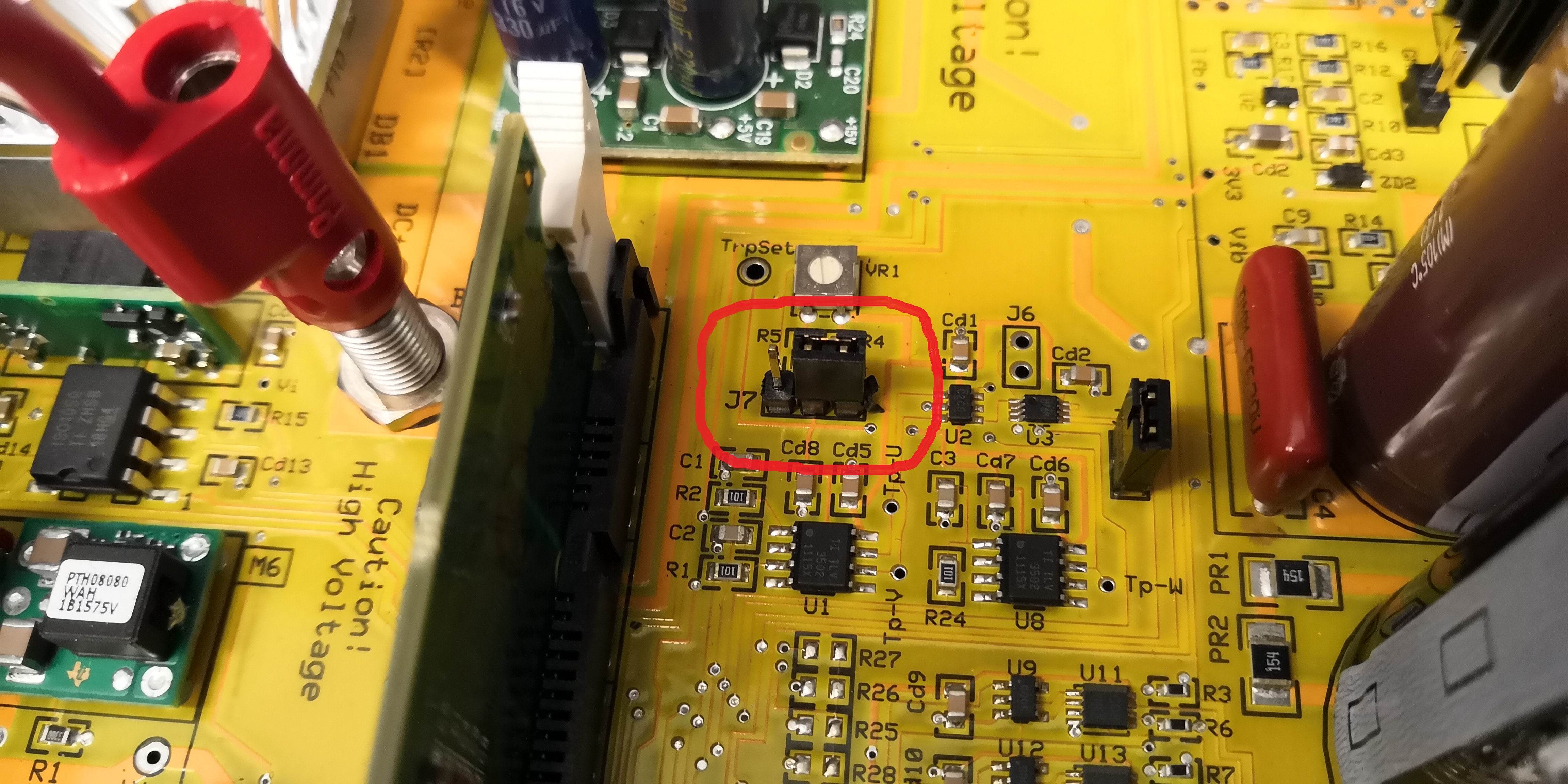
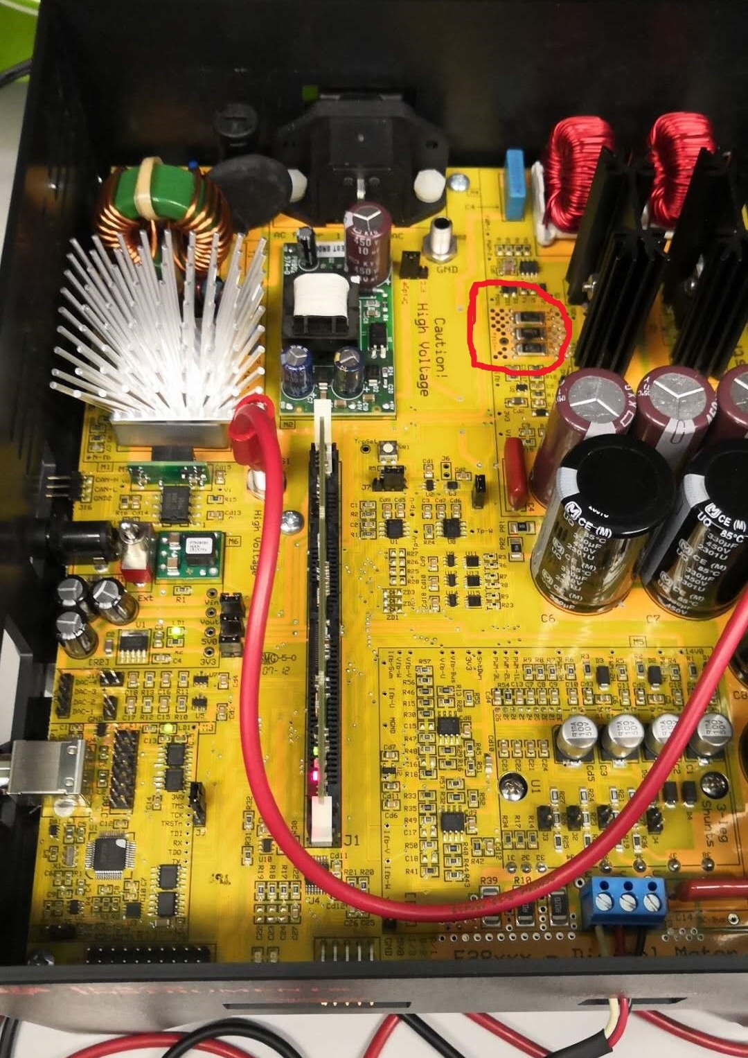
But when I was doing the step(4) at section "Running the GUI" and "connect the other end of the AC power cord to mains/wall power outlet", the three resister on the KIT which called [M4]-R18, [M4]-R6, [M4]-R8 (the red circle inside the attached picture) suddenly burned.

Can you kindly tell me what cause the burning of these three resisters? And whether these three resisters are necessary for me to run the PMSM motor? Even can I replace them with a wire because the value of them is only 0.05 ohm(R05F)

  • Which example project did you run? These resistors are used to implement PFC, you should bypass this module if you don't use any PFC function in your project by connecting BS1 to BS5, not to BS4.
    And you can remove these damaged resistors or replace them with any other resistor if you only want to run motor control.
  • Dear Yanming:
    Thank you for your timely reply.
    I am doing the HV motor control example project with F28035 and PMSM. I should followed the description that in the document when I was preparing for this experiment but I can't confirm whether I connected the BS1 to BS5 or BS4 cause they are too close, So I'm not sure whether your reply can resolve my issue. I'll feedback once I confirm it.

    Best regards
    K.K
  • You may bypass the PFC by connecting the BS1 to BS5 without doing anything else.
  • Dear Yanming:

    Thank you for your attention.

    I checked my kit today and I have truely connected the BS1 to BS5. The only thing that I don't sure is whether the position of [main]-J7 is right or not?

    Document description: [Main]-J7 is populated between pins 2-3 ( pins furthest from the DIMM 100 socket)

  • As the schematic of HVkit, J7 is used for setting the trip reference voltage of over current protection. Please be noted that the HVkit is hot ground design, and please be careful to connect PC, Oscilloscope and HVkit using the same ground of AC power supply, it's better to use isolated AC power supply for HVkit.
    Btw, please make sure that the jumpers & connector settings are valid as the user guide of HVkit before you apply the AC power to the board.