This thread has been locked.

If you have a related question, please click the "Ask a related question" button in the top right corner. The newly created question will be automatically linked to this question.

CCS/TMS320F2808: F2808

Part Number: TMS320F2808


Tool/software: Code Composer Studio

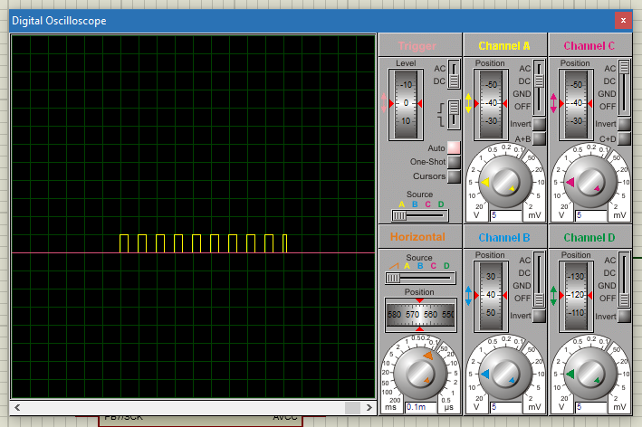
I am trying to create a pulse train. The span of the pulse train is 1msec. The time period of a single pulse is 100usec. I am using timer0 to generate CMPA value of ePWM1. The code is as follows

%%%%%%%%%%%%%%%%%%%%%%%%%%%%%%%%%%%%%%%%%%%%%%%%

#include "DSP280x_Device.h"
#include "DSP280x_Examples.h"

int i=0;

typedef struct
{
volatile struct EPWM_REGS *EPwmRegHandle;
}EPWM_INFO;


void InitEPwm1Example(void);

__interrupt void cpu_timer0_isr(void);

void main(void)
{

InitSysCtrl();

InitEPwm1Gpio();

DINT;

InitPieCtrl();

IER = 0x0000;
IFR = 0x0000;

InitPieVectTable();

EALLOW;
PieVectTable.TINT0 = &cpu_timer0_isr;
EDIS;

InitCpuTimers();

ConfigCpuTimer(&CpuTimer0, 100, 1000); \\ Clock Frequency 1kHz
CpuTimer0Regs.TCR.all = 0x4000;

EALLOW;
SysCtrlRegs.PCLKCR0.bit.TBCLKSYNC = 0;
EDIS;

InitEPwm1Example();

EALLOW;
SysCtrlRegs.PCLKCR0.bit.TBCLKSYNC = 1;
EDIS;

IER |= M_INT3;
IER |= M_INT1;

PieCtrlRegs.PIEIER1.bit.INTx7 = 1;

EINT;
ERTM;

for(;;)
{
__asm("NOP");
}
}

__interrupt void cpu_timer0_isr(void)
{

if(i<1)
{
EPwm1Regs.CMPA.half.CMPA = 2110;
}
else
{
EPwm1Regs.CMPA.half.CMPA = 0;
}

i=i+1;
if(i>19)
{
i=0;
}

PieCtrlRegs.PIEACK.all = PIEACK_GROUP1;
}

void InitEPwm1Example()
{

EPwm1Regs.TBPRD = 2500; \\ PWM frequency 10kHz
EPwm1Regs.TBPHS.half.TBPHS = 0x0000;
EPwm1Regs.TBCTR = 0x0000;


EPwm1Regs.CMPA.half.CMPA = 0;


EPwm1Regs.TBCTL.bit.CTRMODE = TB_COUNT_UPDOWN;
EPwm1Regs.TBCTL.bit.PHSEN = TB_DISABLE;
EPwm1Regs.TBCTL.bit.HSPCLKDIV = TB_DIV2;
EPwm1Regs.TBCTL.bit.CLKDIV = TB_DIV1;


EPwm1Regs.AQCTLA.bit.CAU = AQ_CLEAR;
EPwm1Regs.AQCTLA.bit.CAD = AQ_SET;

EPwm1Regs.CMPCTL.bit.SHDWAMODE = CC_SHADOW;
EPwm1Regs.CMPCTL.bit.LOADAMODE = CC_CTR_ZERO;

}

%%%%%%%%%%%%%%%%%%%%%%%%%%%%%%%%%%%%%%%%%%%%%%%%%%%%%%%%%%%%%%%%%%

A peculiar case happens. Since my pulse train span is 1msec and one pulse is 100usec I have a total of 10 pulses in 1msec. Since I have a constant CMPA value in this 1msec the pulse width should be same but the tenth pulse which is the last pulse has 100% duty ratio. I don't want a PWM interrupt to change the CMPA value I purposefully want a timer interrupt to change the CMPA value. Can anyone please help me fix this issue?

  • These are active low pulses, right? What you seem to be doing is forcing CAU, CAD, and the shadow update all onto the zero match event. Why not leave CMPA alone and just change CAU to AQ_SET to disable the pulses?
    Also, from your CMPA setting it seems to me you should be getting a 15.6us pulse width because (2500 - 2110)*2 = 780, and 100*780/5000 = 15.6% duty.
    Regards,
    Richard
  • Hi Richard. Thanks for replying. Your idea of changing the action qualifier bits is great. Actually, this program is a part of a bigger program. It is basically an inverter program. I have to keep changing the CMPA value after every 1msec creating a pulse train for every 1msec.

    For the program I have given above isn't the duty ration 84%. Clear on up-counting compare match and Set on downcounting compare match which mean most of the time the pulse is held high right?.
  • Yes, that's correct. If you're calling it an active high signal then the duty cycle is 84%. Glad the AQ suggestion helped.
    Regards,
    Richard
  • That wasn't my probem.

    Assume 20msec to be 1 cycle.
    Divide this 20msec in to 20 divisions of 1msec.
    Out of this 20 division, 1 division must possess a train pulse.
    The frequency of each pulse is 10kHz and duty ratio should be 84%.
    Since the frequency of each pulse is 10kHz there has to be 10 pulses in the pulse train and all pulses should be of width 84%

    My problem is that first 9 pulses are of width 84% and last pulse is of width 100%.
  • So, not touching CMPA but just changing the AQ setup in your timer ISR changed nothing?

    As I read your code, you should be getting a timer interrupt just before the PWM zero match. The reason it's just before is because you start the CPU timer before you start the PWM timer, so there is a small lag. I'm wondering if that lag is not enough, so by the time your timer ISR has gone through its' context save the PWM zero event has already passed. What you could try is inserting a small delay (say 100 cycles or so) before starting the PWM timer.

    There are better and easier ways of modulating the pulse train. The difficulty is trying to match timing between two independent counters.

    Regards,

    Richard
  • Is there a way to use a PWM interrupt instead of TIMER interrupt to happen every 1msec? I am operating the PWM at 10kHz frequency.
  • You could configure any unused PWM module to act as a 1ms interrupt timer. With a SYSCLK/2 setup and in UP-COUNT mode, you would set TBPRD to 5000.

    Are your 10kHz and 1ms numbers fixed, or are you going to change these? If not, what I was getting at in my last post was you'd be better off just doing everything from a PWM period interrupt.

    Regards,

    Richard
  •  Greetings,

    My 10kHz and 1msec are fixed.  The only thing I don't understand is why one pulse out of the ten pulses in the pulse train has a different duty ratio.

  • Can you post the PWM setup and interrupt code? I'll be happy to take a look.

    Regards,

    Richard
  • The following is the code used.

    %%%%%%%%%%%%%%%%%%%%%%%%%%%%%


    #include "DSP280x_Device.h"
    #include "DSP280x_Examples.h"

    int i=0;

    typedef struct
    {
    volatile struct EPWM_REGS *EPwmRegHandle;
    }EPWM_INFO;

    void InitEPwm1Example(void);

    __interrupt void cpu_timer0_isr(void);

    void main(void)
    {

    InitSysCtrl();

    InitEPwm1Gpio();

    DINT;

    InitPieCtrl();

    IER = 0x0000;
    IFR = 0x0000;

    InitPieVectTable();

    EALLOW;
    PieVectTable.TINT0 = &cpu_timer0_isr;
    EDIS;

    InitCpuTimers();

    ConfigCpuTimer(&CpuTimer0, 100, 1000); \\ Clock Frequency 1kHz
    CpuTimer0Regs.TCR.all = 0x4000;

    EALLOW;
    SysCtrlRegs.PCLKCR0.bit.TBCLKSYNC = 0;
    EDIS;

    InitEPwm1Example();

    EALLOW;
    SysCtrlRegs.PCLKCR0.bit.TBCLKSYNC = 1;
    EDIS;

    IER |= M_INT3;
    IER |= M_INT1;

    PieCtrlRegs.PIEIER1.bit.INTx7 = 1;

    EINT;
    ERTM;

    for(;;)
    {
    __asm("NOP");
    }
    }

    __interrupt void cpu_timer0_isr(void)
    {

    if(i<1)
    {
    EPwm1Regs.CMPA.half.CMPA = 1125;
    }
    else
    {
    EPwm1Regs.CMPA.half.CMPA = 0;
    }

    i=i+1;
    if(i>19)
    {
    i=0;
    }

    PieCtrlRegs.PIEACK.all = PIEACK_GROUP1;
    }

    void InitEPwm1Example()
    {

    EPwm1Regs.TBPRD = 2500; \\ PWM frequency 10kHz
    EPwm1Regs.TBPHS.half.TBPHS = 0x0000;
    EPwm1Regs.TBCTR = 0x0000;


    EPwm1Regs.CMPA.half.CMPA = 0;


    EPwm1Regs.TBCTL.bit.CTRMODE = TB_COUNT_UPDOWN;
    EPwm1Regs.TBCTL.bit.PHSEN = TB_DISABLE;
    EPwm1Regs.TBCTL.bit.HSPCLKDIV = TB_DIV2;
    EPwm1Regs.TBCTL.bit.CLKDIV = TB_DIV1;


    EPwm1Regs.AQCTLA.bit.CAU = AQ_CLEAR;
    EPwm1Regs.AQCTLA.bit.CAD = AQ_SET;

    EPwm1Regs.CMPCTL.bit.SHDWAMODE = CC_SHADOW;
    EPwm1Regs.CMPCTL.bit.LOADAMODE = CC_CTR_ZERO;

    }
    %%%%%%%%%%%%%%%%%%%%%%%%%%%%%%%%%%%%%%%%%%%%%%%%%%%%%%%%%%%%%%%%%%
  • Apart from the CMPA setting this code looks identical to that in your first post. Yet there you say you were getting 100% duty in the final pulse, and here it's truncated. Is this correct?

    Did you try the PWM interrupt approach above?

    Regards,

    Richard
  • Specifying EPwm1Regs.CMPCTL.bit.LOADAMODE = CC_CTR_ZERO_PRD; fixed the problem. Thank you so much.
  • A pleasure. Glad to know the problem is resolved. Thanks for letting us know.

    Regards,

    Richard