This thread has been locked.

If you have a related question, please click the "Ask a related question" button in the top right corner. The newly created question will be automatically linked to this question.

TMS320F28069: Doubt about estimated rated flux and excesive current

Part Number: TMS320F28069
Other Parts Discussed in Thread: MOTORWARE

Hello!

I have some problems to move the motor with load.

I have performed the identification without problems

#define USER_MOTOR_TYPE MOTOR_Type_Pm

#define USER_MOTOR_NUM_POLE_PAIRS (2)
#define USER_MOTOR_Rr (NULL)
//#define USER_MOTOR_Rs (0.076525)
#define USER_MOTOR_Rs (0.04565098)
#define USER_MOTOR_Ls_d (0.0002467314)
#define USER_MOTOR_Ls_q (0.0002467314)
#define USER_MOTOR_RATED_FLUX (0.107993)
#define USER_MOTOR_MAGNETIZING_CURRENT (NULL)
#define USER_MOTOR_RES_EST_CURRENT (6.0)
#define USER_MOTOR_IND_EST_CURRENT (-2.0)
#define USER_MOTOR_MAX_CURRENT (40)
#define USER_MOTOR_FLUX_EST_FREQ_Hz (13.0)

The theorical motor parameters are:

Rated Power: 320W

Rated Speed: 3220rpm

Vnom = 24V

Inom = 16.7A

Ke = 4.25V/Krpm

Poles = 4

I have some doubts with the inferred Kt (3/2*PolePairs*RatedFlux[V/Hz]/2*pi). If proper units (e.g. V/[rad/s]) are used Ke and Kt should be the same. Is not?

How can I verify that estimated rated flux is correct? What would be the efect of giving an incorrect Rated Flux?

I have attached the motor to another motor to simulated a load. The "load motor" has a torque control with speed limit fixed to 0.

Once I the resistive torque is increased, the current consumed by the board and motor is quite high. More of the 50% is  wasted.

¿Could this problem be related to an incorrect identification?

Thank you in advance

Borja Gómez

  • You may get the parameters from the motor datasheet which should be provided by motor manufacturer. Or you may refer to Sec. 6.8 of InstaSPIN User's Guide (SPRUHJ1) to measure the flux.
    The flux should be identified correctly if the motor run smoothly during the identification process, you may adjust the USER_MOTOR_FLUX_EST_FREQ_Hz to identify the motor again, it looks the USER_MOTOR_FLUX_EST_FREQ_Hz is too lower for the flux identification.
  • Hello!

    I have made some tests with both DRV8301revD and custom board and results for the identification process are the same for both board.

    The identification process is seemed to be done correctly. the motor spins smoothly and no error are reported.

    I have tried to identify the motor with different USER_MOTOR_FLUX_EST_FREQ_Hz. From 11Hz (as recommended in motorware_selecting_user_variables) to 20Hz (bigger value as you adviced me) We have obtained the same results:

    #define USER_MOTOR_NUM_POLE_PAIRS (2)
    #define USER_MOTOR_Rr (NULL)
    #define USER_MOTOR_Rs (0.04565098)
    #define USER_MOTOR_Ls_d (0.0002467314)
    #define USER_MOTOR_Ls_q (0.0002467314)
    #define USER_MOTOR_RATED_FLUX (0.107993)
    #define USER_MOTOR_MAGNETIZING_CURRENT (NULL)
    #define USER_MOTOR_RES_EST_CURRENT (6.0)
    #define USER_MOTOR_IND_EST_CURRENT (-2.0)
    #define USER_MOTOR_MAX_CURRENT (40)
    #define USER_MOTOR_FLUX_EST_FREQ_Hz (13.0)

    I have coupled the motor to another motor ("load motor") (using and elastic couple to absorb the misalignements). The load motor opposed 5Nm to the motor. Once the control is activated the speed is regulated correctly, but the current in the phases seems to be higher than expected.

    The motor axle is connected to a  gear (1:14). So in order to move the other motor a torque of 5/14Nm should be enought (a little bit more depending on the efficiency of motor, gears a coupling elements). 

    The torque that the motor is doing to move the "load motor" is about 1Nm ==> 1Nm*GearRatio = 14Nm to move a load of 5Nm!!!!!

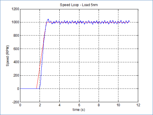
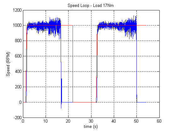
    The following figure shows the speed signal provided by instaspin via CAN

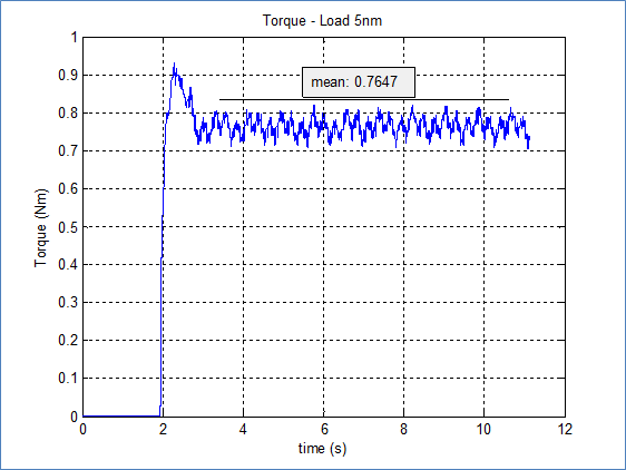
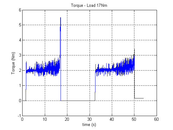
    The following figure shows the torque to be done to move the motor to 1000rpm (with an opposite load of 5Nm).

    The torque is the measured motor torque (T = Iq*Kt).

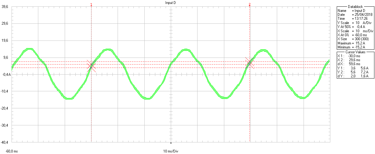
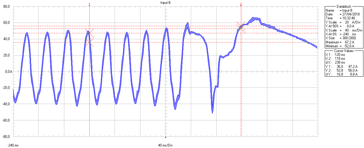
    The following figure shows the current throught the phase A during this test:

    The wave is nearly sinusoidal (f=16.7Hz ==> 1000rpm). The current (15.2) is nearly the rated current of the motor (16,7A).

    The USER_MOTOR_RATED_FLUX  that I have obtained from identification process is 0.108V/Hz

    Flux (Wb) = 0.108/(2*pi) = 0,0172rad/s

    Kt = 3/4*Poles*Flux = 0,0516

    T = 0,0516*15,2 = 0,78432Nm (quite similar to the one obtained from values given by instaspin).

    The Ke given by the motor manufacturer is 4,25V/Krmp

    Ke = 4.25/1000*60/(2*pi) = 0.0406rad/s

    T = 3/4*Poles*Ke *I = 0.2118*I

    Using the parameters given by the manufacturer, the torque to be achive for the Iq values should be higher

    What should be the effect of giving a not correct rated flux parameter in the user.h

    Is there something wrong in my calcules or there is another parameters to be considered during the identification process?

    Thank you in advance

    Borja

    The

  • 1. Often, Ke is motor voltage constant or bemf constant, its unit is volts-sec/rad or v/hz, and Kt is motor torque constant, it unit is lb-lin/amp or N.m/amp.
    2. May you check the Ke is RMS or peak line to line value which given by the motor manufacturer? For RMS, it should be Ke = 4.25/1000*60/2*(SQRT(2)/SQRT(3))=0.1041V/Hz.
    3. What rated frequency is in the motor 's datasheet? Please be noted that the sensorless instaSPIN-FOC is difficult to work well with low speed though you are using torque control mode.

  • Dear Yanming

    Thank you for your repply.

    I have realized that we have an effieciency issue. The gearbox and motor has an efficiency poorer than expected (75% and 80% respectively), so we waste too much energy. 

    I have a doubt about the 3rd point. As you say we have seen that starting from zero speed could be a problem. Is there any difference if we use speed control instead of torque control? This motor will be used in an AVG vehicle so multiple instaspin control will run simultaneously to drive each wheel of the vehicle. How can affect this?

    Thank you in advance

    Borja

  • Dear Yanming

    2. May you check the Ke is RMS or peak line to line value which given by the motor manufacturer? For RMS, it should be Ke = 4.25/1000*60/2*(SQRT(2)/SQRT(3))=0.1041V/Hz.

    The unit of KE is V/KRPM. The value is RMS volts between phase to phase

    What is the correct one?

    This 4.25/1000*60/2*(sqrt(2)/sqrt(3)) = 0.1041V/Hz

    or this one: 4.25/1000*60/(2*PI)*(sqrt(2)/sqrt(3)) = 0.0331V/Hz?

    The problem of the waste of torque I think is more or less solved. We have realized that we have an efficiency problem (Motor + Gearbox efficiency is not very good), but we have still problems with high torques

    We have managed to start the motor from 0 to 1000rpm with a load of 14Nm. We have maintain the 1000rpm speed reference. It seemed to work OK but the torque and speed ripple were increasing progresively and suddenly there has been a huge increment in the torque (electric) and the system has shut down. This shutdown was due to the driver, The driver though that there was a shortcircuit and have switched off the control. There has no been voltage fault in the power supply.

    We have seen that the time that the control remains estable depends on the value of USER_IQ_FULL_SCALE_VOLTAGE_V? For instance if USER_IQ_FULL_SCALE_VOLTAGE_V = 24V the system takes more time to set the fault than with a value of 48V. Is that possible?

    The following figures

    ADC = 1.65 + 20Vsense = 1.65+20(Isense/Rsense) = 50A

    The following figure shown the current though phase A

    The speed and the torque are shown in the following figure (once 17Nm load is applied the app suddenly stops)

    The HW was fixed to measure 41.25A and then it has been modified to measure 82.5A (165Vpp with and Rs of 1mOhm) so ADCs should not be saturated.

    It seems that something is being saturated or unestable, but I do not figure out what?

    Any clue?

    Thank you in advance

  • Borja Gomez88 said:

    We have seen that the time that the control remains estable depends on the value of USER_IQ_FULL_SCALE_VOLTAGE_V? For instance if USER_IQ_FULL_SCALE_VOLTAGE_V = 24V the system takes more time to set the fault than with a value of 48V. Is that possible?

    Could you test if this behavior is influenced by disabling DC bus compensation? In some uncommon situations, mostly related to oddball scales, the DC bus compensation overflows the current controller Kp values which causes instability. If you set your USER_IQ_FULL_SCALE_VOLTAGE_V to twice the actual bus voltage (which should be no problem), the DC bus compensation doubles your effective current PId Kps. If these are already very high, say 70, they get doubled to 140, which is over the 128 limit for an iq24 number, and the calculation wraps.

  • Hello

    I have tried to disabled the DC bus compensation with no result.

    We have realized that probably our Rsense was too low. So the measurement circuit has been changed slighly:

    The original circuit:

    Vadc = 1.65 + 20*Isense*Rsense ( Rsense = 0.001) ==> Isense = +/-82.25A

    #define USER_IQ_FULL_SCALE_CURRENT_A        (83.0)     // Rs: 0.001 G: 20

    #define USER_ADC_FULL_SCALE_CURRENT_A        (165.0)     // Rs: 0.001 G: 20

    We have increased the  Rsense value and decreased the Gain of the amp op:

    Vadc = 1.65 + 12*Isense*Rsense (Rsense = 0.002) ==> Isense = +/- 68.75A (Enought for our app)

    #define USER_IQ_FULL_SCALE_CURRENT_A        (69.0)     // Rs: 0.001 G: 12

    #define USER_ADC_FULL_SCALE_CURRENT_A        (137.5)     // Rs: 0.002 G: 12

    The voltage measurement circuit is the same:

    Vadc = Vphase*10K/(10K + 82K) ==> If Vadc = 3.3V ==> Vpahse| Max =  30.36V

    for our app Vdc|link = 24V

    #define USER_IQ_FULL_SCALE_VOLTAGE_V      (24.0)

    #define USER_ADC_FULL_SCALE_VOLTAGE_V       (30.36)

    A 47nF filter has been to filter this voltage:

    Frec = 1/(82K*10K/(82K+10K)*47nF*2*pi) = 379.92358

    #define USER_VOLTAGE_FILTER_POLE_Hz  (379.92358)

    We have tested the system with these conditions:

    Load torque: 1.56Nm (164%Tn) (This is the torque to be applied in the motor to move the load at 1000rpm if effienciency of the gear, motor and control is considered)

    Speed: 1000rpm (33%Wn)

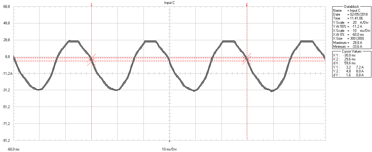
    Above this 1.04Nm the current started to saturate and it seems not to be symmetrical. Current magnitudes verify (more or less) the torque equation:  T = Kt*Iq  ==> Kt = 0.05 ==> Iq = 31.2A

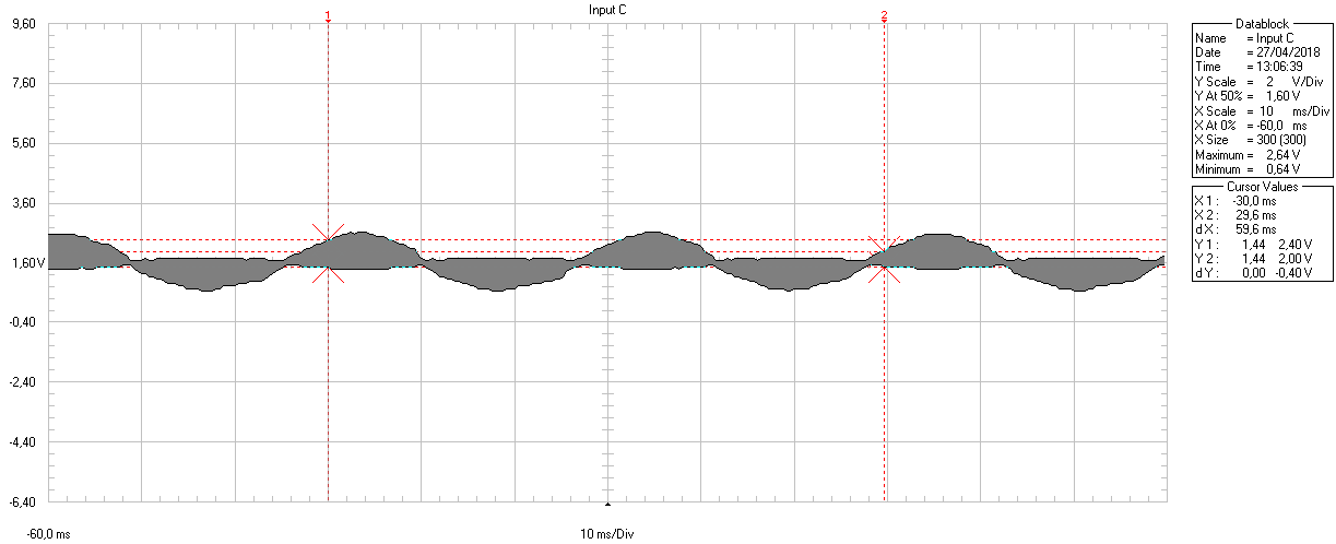
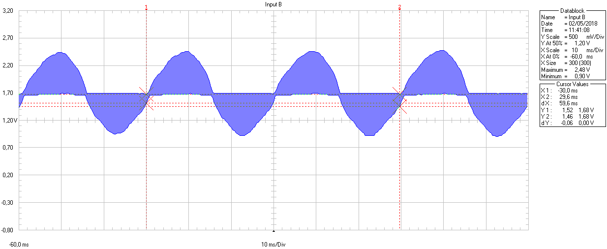
    The following figure shows the input to the ADC channel for phase U. This wave is not saturated and the offset seems to be around 1.65V

    This saturation does not allow us to increase the torque (It is needed for some cases)

    What could be the cause of this saturation? The ADC input seems to be OK. Is there any configuration parameter that could somehow saturate (not symetrically) the variables (currents, voltages, ...)?

    Thank you in advance

    Borja

  • Hello!

    Finally I think the issue is solved. The wave was not saturated. there was a problem in the current probe.

    Then, we have realized the one of the current path is not wide enough to manage such a high current. We have improve this path and the system seems to work ok (current mesasurement circuit changes alse help). We can manage the motor even with high loads (200% Tn). Startup should be improved, but this is another issue and I will try to solve with halls.

    Thank you from your help

    Borja