This thread has been locked.

If you have a related question, please click the "Ask a related question" button in the top right corner. The newly created question will be automatically linked to this question.

TMS320F28379D: SPI Slave corrupts received data by sending data out. Driverlib

Part Number: TMS320F28379D


Hi,

Sorry if the Title is confusing. I am working on a 28379D Launchpad with SPIB configured as a Slave. I have an external device that sends 5 bytes to the Slave. I am using Driverlib to configure the Slave peripheral. My configuration sequence is as follows:

- Disable SPIB
- Register SPIB_RX with function pointer
- Configure GPIOs
- Configure SPI, phase, slave, 500kHz, 8bit word
- Enable FIFO on SPIB
- Clear IRQ Status for RXFF
- Set FIFO Level to TX1, RX5
- Enable IRQ RXFF
- Enable SPIB module
- Enable SPIB RX IRQ

The data I am sending is: 0x20 0x48 0xAA 0x00 0x00 pretty basic. I can see the RX interrupt being thrown and data being available.

I've confirmed signals on the SPI lines with my scope. Pretty straight forward too.

The issue I am having with the Slave is that it sends data out on the MISO line even though I physically do not have any code that writes any data to the TX buffer.

What is even stranger, data comes out on the MISO pin and corrupts the data on the MOSI. Almost every second transmission, the 3rd byte is processed as 0xB5 and not as 0xAA. Please see images below.

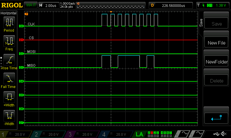
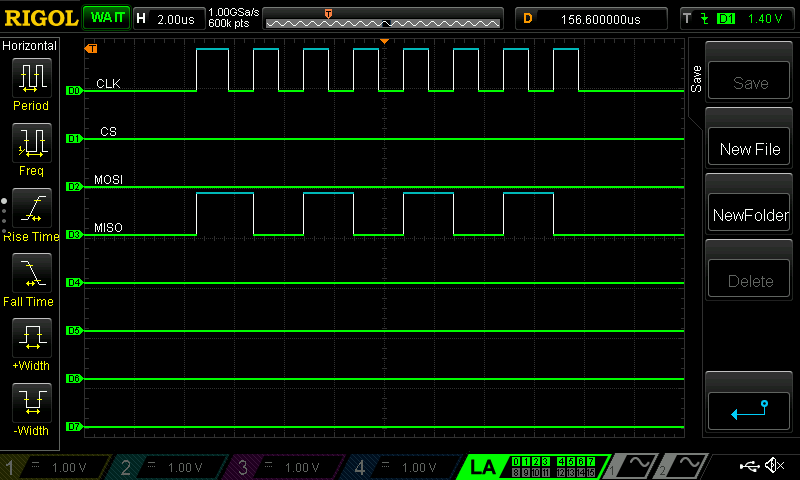
This first image shows data 0x20 0x48 0xAA 0x00 0x00  being transmitted to the Slave. iYou will notice that the Slave is responding with data on the MISO even though I've not told it to send anything. In this example the Delfino correctly receives the 3rd byte as 0xAA.

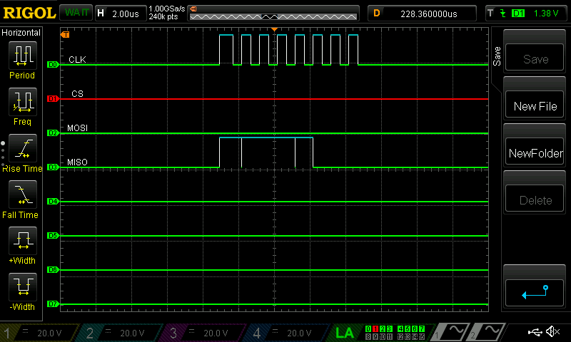
In this example below, the Master is sending identical data again, however this time the slave very briefly pulls the MISO line high. In this example the Slave thinks the 3rd byte is 0x5B.

Any advice would be much appreciated.

  • Dainius,

    Data coming out of MISO pin isn't a strange behavior. That is how SPI hardware is implemented because SPIDAT is essentially a shift register.

    Clearing TALK bit (SPICTL.TALK = 0) will put MISO pin in high impedance state and the data will not echo back.

    Regards,

    Manoj

  • Hi Manoj,

    So I have re-wrote the way I was processing the received bytes. Now the RX IRQ is thrown every word (8 bits) and I receive all data as expected. Received data is not getting corrupted. I have to keep writing zeros to avoid data corruption, but anyway it does seem to work.

    In addition, I have progressed with implementing responses from the Slave, majority works well, however the Slave (F28379D) seems to sometimes (75% of the time) fail to clock the MISO bits correctly. The Slave is suppose to send value 0xBA. Sometimes is sends it fine, sometimes it misses the CLK.

    Below is example of what a correct response is. Slave responds with 0xBA.

    If I send requests one after another to send back 0xBA, sometimes the returned data is messed up. The slave return 0xF8 instead of 0xBA.

    The Bitrate is set to 1MHz, and the Master is in SPI mode 1, and Slave is in mode 0.

  • Dainius,

    Its not clear from your message whether you tried my suggestion.

    Regards,

    Manoj

  • Manoj,

    My apologies. I have tried your suggestion. The driverlib does not implement ability to set the TALK bit separately, so I wrote functions myself

    static inline void spi_disable_slave_output(uint32_t base)
    {
    	HWREGH(base + SPI_O_CTL) &= ~(SPI_CTL_TALK);
    }
    
    static inline void spi_enable_slave_output(uint32_t base)
    {
    	HWREGH(base + SPI_O_CTL) |= SPI_CTL_TALK;
    }

    I've also updated the initialisation sequence to 

    - Disable SPIB
    - Register SPIB_RX with function pointer
    - Configure GPIOs
    - Configure SPI, phase, slave, 500kHz, 8bit word
    - Disable Slave output
    - Enable FIFO on SPIB
    - Clear IRQ Status for RXFF
    - Set FIFO Level to TX1, RX5
    - Enable IRQ RXFF
    - Enable SPIB module
    - Enable SPIB RX IRQ

    When the RX IRQ is thrown at each byte reception the TALK bit is 0, the TALK flag would get enabled after the second byte is received and my code would not clear the TALK bit until all 5 bytes have been receive. However, what the oscilloscope traces show was that the MISO stays HIGH until the second byte, then as the 3rd byte is clocked the MISO stays low, pressume it thinks I am sending value 0, and then the MISO line return to HIGH for the remaining two bytes (even though the code has not put the TALK bit to 0).

  • Manoj,

    In addition to my most recent reply, I would like to give you more information. I have implemented the TALK flag toggling throughout the transmission. As before, I am trying to use the SPI bus to receive data from the Slave. At the moment the Slave is suppose to reply 2 bytes of data 0xAA 0xAA.

    The image below, shows the MISO signal being HIGH until, the TALK flag is set by my software. The Slave sends 2 bytes and the software sets the MISO back to HIGH.

    I am feeling much happier now that I understand a bit more about the TALK bit. However, I had to make some strange function calls to make this work. Please see below:

    else if(READ_TWO_BYTES == request_internal.code)
    {
        uint16_t upper = (read & 0xFF00);
        uint16_t lower = (read & 0x00FF);
        SPI_resetRxFIFO(DEVICE_SPI_BASE);                         //<--- Had to add this to stop sending data that was just received
        SPI_resetTxFIFO(DEVICE_SPI_BASE);                         //<--- Had to add this to stop sending data that was just received
        spi_enable_slave_output(DEVICE_SPI_BASE);                 //<--- This is my custom function to set TALK = 1
        SPI_writeDataBlockingFIFO(DEVICE_SPI_BASE, upper);
        SPI_writeDataBlockingFIFO(DEVICE_SPI_BASE, (lower << 8));
    }

    Everything seems to be pretty good in this configuration other than the fact that the signals on the MISO line are corrupt. Here is a closer view.

    Here is a good 0xAA.

    Here is the last byte of the transmission. Should be 0xAA, but it gets processed as 0xED.

    I should point out that most of the time, both bytes get corrupted, not just the last one. I've confirmed via the CSS debugger that the code is actually sending 0xAA for both bytes.

    I really appreciate your support.

  • Hi,

    Quick question:

    What is your master in this situation? You state that the master and slave are using different modes:

    Dainius Narsutis57 said:
    The Bitrate is set to 1MHz, and the Master is in SPI mode 1, and Slave is in mode 0.

    If these are both C2000 devices, you want the modes to match between the master and slave. The data needs to be put out on one edge and latched in on the other.

    Please clarify, in CCS, you see that the data is being transmitted and received properly as 0xAA ? but the scope is not registering it properly? What type of scope and probe are you using?  is it the digital probes of your scope? What does the raw signal look like on the scope?

    -Mark

  • Hi Mark,

    Thank you for your interest in my post.

    While I am waiting for a Sitara AM-335x based SOM to arrive (that will act as a Master in project eventualy), I have purchased one of these USB-SPI breakout modules. The MCP2210 IC (datasheet) implements all 4 SPI modes.

    I know they sometimes they are implemented differently between manufacturers, but fundamentally, what I found is that if the TI's Delfino is in Mode 0, and Microchip's MCP2210 is in Mode 1, the Slave can receive the sent data from the Master and the Master can receive the sent data from the Slave. Maybe it is a coincidence.

    In CCS I can see both bytes to be sent as 0xAA 0xAA, when the signals are captured by my RIGOL MSO1104Z Oscilloscope with Logic Analyser (RPL1116) adapter attached to it, the SOMI signals are a mess as shown in the images above.

    I have not looked at the raw traces yet, I will capture some traces and report back.

    Much appreciated.

  • I am back with a virtual tail between my legs.

    I've decided to start from scratch, everything unplugged. As I was unplugging wires, I've noticed that my Saleae LA was not properly disconnected. I used the Saleae LA before the oscilloscope. I've disconnected its cables from my CLK, CS, MISO, MOSI that were going between the Oscilloscope's LA and the Delfino and what do you know, data corruption disappeared and I can clearly see the data I was expecting.

    Yep folks -  a brain fart. I will not get back these 3 days I've spent troubleshooting this.

    Thank you Mark. I think I should invest into a rubber duck.

  • Dainius,
    Glad to hear that you were able to resolve the issue and I think everyone here understands your pain.

    Regards,
    Mark