Hi all,
Introduction:
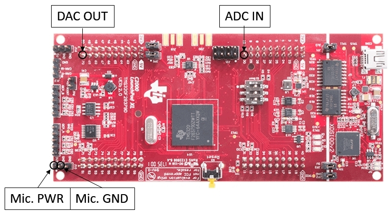
I am working on an acoustic sensor for echolocation using F28379D (Ver: 2.0). The sensor consists of a speaker (250ST/R160) and a microphone (SPU0410LR5H-QB), the speaker emits a 25kHz sine wave (Vpp of 24V) and when the microphone receives the echo, it converts acoustical energy (sound waves) into electrical energy (the audio signal). This signal is fed to the ADC (Pin #30), which samples the signal at 250kHz (10 points per period).
The sequence of action is as follows:
- The sensor turns left.
- Turn ON the speaker, emit a sine wave for 0.5ms, turn OFF the speaker.
- Do nothing for 1ms.
- Turn ON the ADC, stay ON for 5ms, turn OFF the ADC.
- The sensor turns right and then this process is repeated.
This is how it looks in the oscilloscope:
Blue signal is the Microphone sensor reading, yellow signal is the ADC reading (outputted from the DAC).
The circuit:
What was the initial problem?
The purpose is to determine which side of the sensor, the object is located by comparing the maximum reading in the left ADC window to the max reading of the right ADC window.
As you can see (in Figure 1) the amplitude of the echo on the RHS is significantly larger (compared to the LHS), showing that the sensor is doing what it is supposed to do yet the max amplitudes of the ADC readings are almost the same, making it impossible to determine where the object is located.
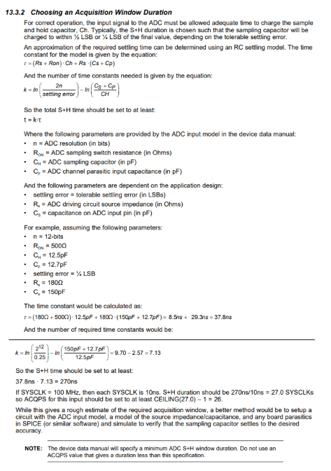
I found out that although the ADC is configured to sampled at 250kHz, the frequency of the ePWM signal (that triggers the conversions) was 500kHz. This was something I changed on purpose (to see if the readings are getting more accurate) and apparently I forgot to change it back to what it was. Question: Is this the actually reason why the ADC readings were not proportional to the amplitude of the signal that is being fed in?
What is the current problem?
I wrote a code that initiates a timer and counts the time taken until a reading that is greater than a given threshold value is received. The purpose of this code is to determine how far the object is located as well as the direction at which it is located. Although, I cannot display the max amplitude in real time, I found a reasonable threshold value by try and error (using LEDs as indicators). Question: Can I use the following formula to calculate the threshold value? Threshold = V_measured * (4096/3.3) where V_measured is the voltage measured by the oscilloscope.
The problem is that although the code successfully detects the farness of the obstacle, timing the interval of which max echo is received is not helpful since the echo is only detected right after the ADC window is turned ON (measured time is ≈ 0) and disappears when the obstacle is placed further way, despite the fact that the obstacle is still within the measurement range of the sensor. Question: What could be a possible reason to this strange behavior?


