This thread has been locked.

If you have a related question, please click the "Ask a related question" button in the top right corner. The newly created question will be automatically linked to this question.

TMS320F28062: ADC simultaneous sampling issue

Part Number: TMS320F28062


Hi,

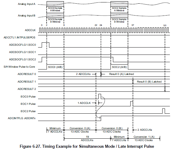
I am using TMS320F28062 processor's internal ADC to capture 4 signals, they are paired in 2 simultaneous sampling pair A0-B0 and A1-B1. 

First pair's start of sampling is triggered by EPWM signal at 20KHz, once the these signals are converted ADC generate an ISR.

In this ISR I use software trigger to start sampling of second pair of signal and wait for conversation to be finish.

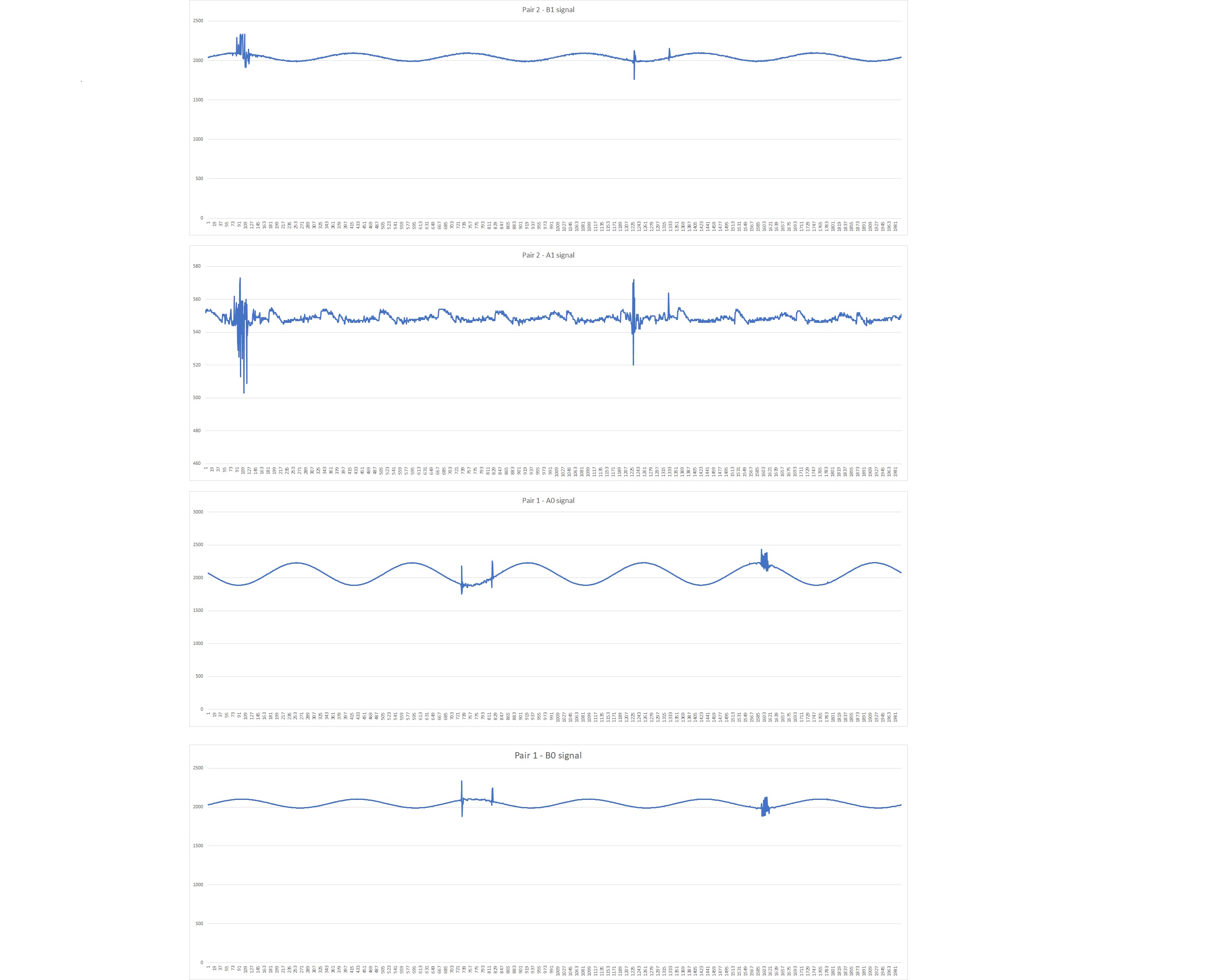
All the RAW ADC values are saved in 4 unsigned int array of 2000 size.

1. first pair of signals gets distortion at exactly same sampling point.

2. Second pair of signals get distortion on exactly same sampling point but different than first pair.

3. All these signals have filter of R=100 ohm and C = 1 microF

Question:

1. Do I have to use any fix delay between pair one end of convertion and pair 2 start of sampling.?

2. Is there any need for discharging the internal S/H capacitor between samples.?

3. any limit on sampling frequency for simultaneous sampling?

Thanks

  • How big is your distortion?  Make sure to check the Errata for ADC advisories in case they are affecting your conversions.

    G.Bull2048 said:
    1. Do I have to use any fix delay between pair one end of convertion and pair 2 start of sampling.?

    There is no requirement for time delay between conversions. In fact, you can trigger both pairs of conversions using the same trigger and the ADC sequencer will process them back-to-back.

    G.Bull2048 said:
    2. Is there any need for discharging the internal S/H capacitor between samples.?

    The S/H capacitor is not preconditioned to a known voltage between conversions so there isn't so much a need to discharge the S/H capacitor between samples as there is the need for the S/H capacitor to settle within the ACQPS window for each sample.  Your 1uF capacitor is large enough to where I would expect it to charge up the S/H capacitors very quickly.  You can check the pin with a scope to see if there might be ringing when the S/H capacitor is connected.

    G.Bull2048 said:
    3. any limit on sampling frequency for simultaneous sampling?

    Generally, the sampling frequency is limited by the ADC operating conditions from the datasheet:

  •  Distortion in ADC RAW values is around +/- 200. see attached file

  • Ok, that's a pretty big distortion.  I would recommend trying this experiment where you change the program:

    1. Add about 80 to the ADCOFFTRIM value
    2. Enable VREFLOCONV and TEMPCONV in ADCCTL1
    3. Replace your two ADC sampling pairs with A5/B5

    If the ADC conversions on A5/B5 have similar distortions, then something is probably disturbing the ADC internal circuitry.  If the A5/B5 conversions are clean, then something is probably coupling onto your A0/B0 and A1/B1 inputs.

  • Lee,

    Test 1

    1. Added 80 to ADCOFFTRIM value.

    2. Enable VREFLOCONV and TEMPCONV in ADCCTL1

    3. Replace ADC Sampling pari with A5/B5.

    disable other pair.

    Result : ADC RAW values dose not show previous distortion. see attached image.

    Test 2

    1. remove the software trigger and trigger all signals from one EPWM trigger.

    Result: ADC raw values for second pair show less distortion than original settings. First pair has same distortion. see attacheg image.

  • G.Bull,

    Is my understanding correct that the distortion goes away if any one pair is eliminated or replaced with A5/B5?

    Can you update the SOCs so that you convert Pair 1 -> Pair 2 -> Pair 1 using a single EPWM trigger? This would help me see if the error might be isolated to just the first SOC.

    Are the 1uF filtering caps close to the ADC pins? Is there any way that noise could be coupling between the 1uF cap and ADC pin? Does increasing ACQPS help?

    -Tommy
  • G.Bull,

    It has been two weeks since your last update. I assume that you were able to resolve your issue. If this isn’t the case, please reject this resolution and reply to this thread. If this thread is locked, please make a new thread describing the current status of your issue.

    -Tommy
  • Tommy,

    I appologies for delayed response. I was on another task,

    last status:

    1. Increase filler capacitor on the sensor side to 1 micro F and resister to 100 ohm.

    2. Added another 1 micro F capacitor near  microprocessors.

    Distortion is significatly less than perivious results. But there is still a distortion.

    Note:

    In a circuit there is a H bridge for power conversion around 1500 W and 350 VDC. As I change the switching frequency of these switches distortion is less or more frequent. And its on different positions on sinewave with different switching frequency.

  • G.Bull,

    My gut feeling is that there is board-level noise coupling. Are you thinking the same thing?

    Do you think that you would be able to identify which signals are aggressing your ADC channels?

    If it is coupling, you might be able to manipulate your ADC SOC triggers to avoid the switching noise. Ideally, it would be best to modify the layout to isolate the signals.

    -Tommy
  • G.Bull,

    I haven't heard from you in a while. Are you still working on this issue?

    -Tommy
  • Tommy,

    Not working on this issue at the moment but will start working on it next week. last status is the same as priviously mentioned.

    Thanks,

    G.Bull