Part Number: TMS320F28379D
Other Parts Discussed in Thread: C2000WARE,
Hi,
My supervisor asked me to use time interrupt instead of the epwm to trigger the adc and as a result I amended the adc_soc_epwm example to be triggered by the cpu timer0 as in the following program code.
The algorithm works but then I noticed that the sampling period is incorrect when I changed the sampling period from 83.33 microsecond to 41.665 microsecond, the adc results which is shown in the pictures below for both case showed that the sampling period still the same which is 83.33 microsecond which is resulted in that the input signal become as a 1 kHz but it's actually 2 khz square wave.
//###########################################################################
//
// FILE: adc_soc_epwm_cpu01.c
//
// TITLE: ADC triggering via epwm for F2837xD.
//
//! \addtogroup cpu01_example_list
//! <h1> ADC ePWM Triggering (adc_soc_epwm)</h1>
//!
//! This example sets up the ePWM to periodically trigger the ADC.
//!
//! After the program runs, the memory will contain:\n
//! - \b AdcaResults \b: A sequence of analog-to-digital conversion samples from
//! pin A0. The time between samples is determined based on the period
//! of the ePWM timer.
//
//###########################################################################
// $TI Release: F2837xD Support Library v210 $
// $Release Date: Tue Nov 1 14:46:15 CDT 2016 $
// $Copyright: Copyright (C) 2013-2016 Texas Instruments Incorporated -
// http://www.ti.com/ ALL RIGHTS RESERVED $
//###########################################################################
//
// Included Files
//
#include "F28x_Project.h"
#include "stdio.h"
#include "math.h"
#include <string.h>
#include <stdlib.h>
#include <file.h>
//
// Function Prototypes
//
void ConfigureADC(void);
void ConfigureEPWM(void);
void SetupADCTimer0(Uint16 channel);
//void SetupADCEpwm(Uint16 channel);
__interrupt void cpu_timer0_isr(void);
void scia_echoback_init(void);
void scia_fifo_init(void);
void scia_xmit(int a);
void scia_msg(char *msg);
void send_result(Uint16 res);
//
// Defines
//
#define RESULTS_BUFFER_SIZE 64 // the buffer size was 256
FILE *myFile;
//#define ADC_SAMPLE_PERIOD 0x1000 // 1999 = 50 kHz sampling w/ 100 MHz ePWM clock
//
// Globals
//
Uint16 AdcaResults[RESULTS_BUFFER_SIZE];
Uint16 AdcaResults1[RESULTS_BUFFER_SIZE];
Uint16 resultsIndex;
Uint16 resultsIndex1;
//Uint16 LoopCount; // from sci example
volatile Uint16 bufferFull;
volatile Uint16 bufferFull1;
Uint16 Vin;
int z;
char *msg;
void main(void)
{
//
// Step 1. Initialize System Control:
// PLL, WatchDog, enable Peripheral Clocks
// This example function is found in the F2837xD_SysCtrl.c file.
//
InitSysCtrl();
//
// Step 2. Initialize GPIO:
// This example function is found in the F2837xD_Gpio.c file and
// illustrates how to set the GPIO to it's default state.
//
InitGpio(); // Skipped for this example
//
// Step 3. Clear all interrupts and initialize PIE vector table:
// Disable CPU interrupts
//
DINT;
//
// Initialize the PIE control registers to their default state.
// The default state is all PIE interrupts disabled and flags
// are cleared.
// This function is found in the F2837xD_PieCtrl.c file.
//
InitPieCtrl();
//
// Disable CPU interrupts and clear all CPU interrupt flags:
//
IER = 0x0000;
IFR = 0x0000;
//
// Initialize the PIE vector table with pointers to the shell Interrupt
// Service Routines (ISR).
// This will populate the entire table, even if the interrupt
// is not used in this example. This is useful for debug purposes.
// The shell ISR routines are found in F2837xD_DefaultIsr.c.
// This function is found in F2837xD_PieVect.c.
//
InitPieVectTable();
//
// Map ISR functions
//
EALLOW;
PieVectTable.TIMER0_INT = &cpu_timer0_isr;
EDIS;
// Initiating the Cpu Timer and configuring it
InitCpuTimers(); // For this example, only initialize the Cpu Timers
ConfigCpuTimer(&CpuTimer0, 200, 83.33); // configuring cpu clock to 200 MHz and interrupt of 12 kHz
//
// Configure the ADC and power it up
//
ConfigureADC();
//
// Configure the ePWM
//
// ConfigureEPWM();
//
// Setup the ADC for ePWM triggered conversions on channel 0
//
SetupADCTimer0(0);
//
// Enable global Interrupts and higher priority real-time debug events:
//
IER |= M_INT1; //Enable group 1 interrupts
EINT; // Enable Global interrupt INTM
ERTM; // Enable Global realtime interrupt DBGM
//
// Initialize results buffer
//
for(resultsIndex = 0; resultsIndex < RESULTS_BUFFER_SIZE; resultsIndex++)
{
AdcaResults[resultsIndex] = 0;
}
resultsIndex = 0;
bufferFull = 0;
for(resultsIndex1 = 0; resultsIndex1 < RESULTS_BUFFER_SIZE; resultsIndex1++)
{
AdcaResults1[resultsIndex1] = 0;
}
resultsIndex1 = 0;
bufferFull1 = 0;
//
// enable PIE interrupt
//
PieCtrlRegs.PIEIER1.bit.INTx7 = 1;
//
// For this example, only init the pins for the SCI-A port.
// GPIO_SetupPinMux() - Sets the GPxMUX1/2 and GPyMUX1/2 register bits
// GPIO_SetupPinOptions() - Sets the direction and configuration of the GPIOS
// These functions are found in the F2837xD_Gpio.c file.
//
GPIO_SetupPinMux(28, GPIO_MUX_CPU1, 1);
GPIO_SetupPinOptions(28, GPIO_INPUT, GPIO_PUSHPULL);
GPIO_SetupPinMux(29, GPIO_MUX_CPU1, 1);
GPIO_SetupPinOptions(29, GPIO_OUTPUT, GPIO_ASYNC);
scia_fifo_init(); // Initialize the SCI FIFO
scia_echoback_init(); // Initialize SCI for echoback
msg = "\r\n\nStart of Conversion: \n\n";
scia_msg(msg);
//
// sync ePWM
//
EALLOW;
CpuSysRegs.PCLKCR0.bit.TBCLKSYNC = 1;
CpuTimer0Regs.TCR.all = 0x4000;
//
// Step 5. User specific code, enable __interrupts:
// Configure GPIO34 as a GPIO output pin
//
EALLOW;
GpioCtrlRegs.GPBMUX1.bit.GPIO34 = 0;
GpioCtrlRegs.GPBDIR.bit.GPIO34 = 1;
EDIS;
CpuTimer0.RegsAddr->TCR.bit.TIE = 1;
//
// Use this loop with Cpu.timer trigger
//
do
{
while(!bufferFull);
bufferFull = 0;
asm(" ESTOP0");
}while(1);
}
//
// ConfigureADC - Write ADC configurations and power up the ADC for both
// ADC A and ADC B
//
void ConfigureADC(void)
{
EALLOW;
//
//write configurations
//
AdcaRegs.ADCCTL2.bit.PRESCALE = 6; //set ADCCLK divider to /4 was 6
AdcSetMode(ADC_ADCA, ADC_RESOLUTION_12BIT, ADC_SIGNALMODE_SINGLE);
//
//Set pulse positions to late
//
AdcaRegs.ADCCTL1.bit.INTPULSEPOS = 1;
//
//power up the ADC
//
AdcaRegs.ADCCTL1.bit.ADCPWDNZ = 1;
//
//delay for 1ms to allow ADC time to power up
//
DELAY_US(1000);
EDIS;
}
//
// SetupADCEpwm - Setup ADC EPWM acquisition window
//
//void SetupADCEpwm(Uint16 channel)
void SetupADCTimer0(Uint16 channel)
{
Uint16 acqps;
//
//determine minimum acquisition window (in SYSCLKS) based on resolution
//
if(ADC_RESOLUTION_12BIT == AdcaRegs.ADCCTL2.bit.RESOLUTION)
{
acqps = 14; //75ns
}
else //resolution is 16-bit
{
acqps = 63; //320ns
}
//
//Select the channels to convert and end of conversion flag
//
EALLOW;
AdcaRegs.ADCSOC0CTL.bit.CHSEL = channel; //SOC0 will convert pin A0
AdcaRegs.ADCSOC0CTL.bit.ACQPS = acqps; //sample window is 100 SYSCLK cycles
AdcaRegs.ADCSOC0CTL.bit.TRIGSEL = 1; //trigger on ePWM1 SOCA/C = 5, OR = 1 for cpu.timer0 trigger
AdcaRegs.ADCINTSEL1N2.bit.INT1SEL = 0; //end of SOC0 will set INT1 flag
AdcaRegs.ADCINTSEL1N2.bit.INT1E = 1; //enable INT1 flag
AdcaRegs.ADCINTFLGCLR.bit.ADCINT1 = 1; //make sure INT1 flag is cleared
AdcaRegs.ADCSOC1CTL.bit.CHSEL = 1; //SOC1 will convert pin A1
AdcaRegs.ADCSOC1CTL.bit.ACQPS = acqps; //sample window is 100 SYSCLK cycles
AdcaRegs.ADCSOC1CTL.bit.TRIGSEL = 1; //trigger on ePWM1 SOCA/C = 5, OR = 1 for cpu.timer0 trigger
AdcaRegs.ADCINTSEL1N2.bit.INT1SEL = 0; //end of SOC0 will set INT1 flag
AdcaRegs.ADCINTSEL1N2.bit.INT1E = 1; //enable INT1 flag
AdcaRegs.ADCINTFLGCLR.bit.ADCINT1 = 1; //make sure INT1 flag is cleared
EDIS;
}
//interrupt void timer0_isr(void)
__interrupt void cpu_timer0_isr(void)
{
CpuTimer0.InterruptCount++;
GpioDataRegs.GPBTOGGLE.bit.GPIO34 = 1;
//
// Acknowledge this interrupt to receive more interrupts from group 1
AdcaResults[resultsIndex++] =AdcaResultRegs.ADCRESULT0;
if(RESULTS_BUFFER_SIZE == resultsIndex)
{
myFile = fopen("C:\\ti\\C2000Ware_1_00_03_00_Software\\device_support\\f2837xd\\examples\\cpu1\\adc_soc_epwm\\AdcaResults1.txt","w");
if( myFile == NULL )
{
printf("Error while opening the file.\n");
}
for (z=0;z<RESULTS_BUFFER_SIZE;z++)
{
Vin = AdcaResults[z];
send_result(Vin);
fprintf(myFile,"%d ",Vin);
}
}
else if(RESULTS_BUFFER_SIZE > resultsIndex)
{
fclose(myFile);
}
if(RESULTS_BUFFER_SIZE <= resultsIndex)
{
resultsIndex = 0;
bufferFull = 1;
}
// AdcaResults1[resultsIndex1++] = (float32) AdcaResultRegs.ADCRESULT1 * (float32)(3/3096);
AdcaResults1[resultsIndex1++] = AdcaResultRegs.ADCRESULT1;
if(RESULTS_BUFFER_SIZE <= resultsIndex1)
{
resultsIndex1 = 0;
bufferFull1 = 1;
}
AdcaRegs.ADCINTFLGCLR.bit.ADCINT1 = 1; //clear INT1 flag
PieCtrlRegs.PIEACK.all = PIEACK_GROUP1;
}
//
// scia_echoback_init - Test 1,SCIA DLB, 8-bit word, baud rate 0x000F,
// default, 1 STOP bit, no parity
//
void scia_echoback_init()
{
//
// Note: Clocks were turned on to the SCIA peripheral
// in the InitSysCtrl() function
//
SciaRegs.SCICCR.all = 0x0007; // 1 stop bit, No loopback
// No parity,8 char bits,
// async mode, idle-line protocol
SciaRegs.SCICTL1.all = 0x0003; // enable TX, RX, internal SCICLK,
// Disable RX ERR, SLEEP, TXWAKE
SciaRegs.SCICTL2.all = 0x0003;
SciaRegs.SCICTL2.bit.TXINTENA = 1;
SciaRegs.SCICTL2.bit.RXBKINTENA = 1;
//
// SCIA at 9600 baud
// @LSPCLK = 50 MHz (200 MHz SYSCLK) HBAUD = 0x02 and LBAUD = 0x8B.
// @LSPCLK = 30 MHz (120 MHz SYSCLK) HBAUD = 0x01 and LBAUD = 0x86.
//
SciaRegs.SCIHBAUD.all = 0x0002; // was 0x0002
SciaRegs.SCILBAUD.all = 0x008A; // was 0x008B
SciaRegs.SCICTL1.all = 0x0023; // Relinquish SCI from Reset
}
//
// scia_xmit - Transmit a character from the SCI
//
void scia_xmit(int a)
{
while (SciaRegs.SCIFFTX.bit.TXFFST != 0) {}
SciaRegs.SCITXBUF.all =a;
}
//
// scia_msg - Transmit message via SCIA
//
void scia_msg(char * msg)
{
int i;
i = 0;
while(msg[i] != '\0')
{
scia_xmit(msg[i]);
i++;
}
}
// scia_fifo_init - Initialize the SCI FIFO
//
void scia_fifo_init()
{
SciaRegs.SCIFFTX.all = 0xE040;
SciaRegs.SCIFFRX.all = 0x2044;
SciaRegs.SCIFFCT.all = 0x0;
}
void send_result(Uint16 res)
{
int b3,b2,b1,b0;
b3 = (res/1000)+48;
b2 = ((res%1000)/100)+48;
b1 = ((res%100)/10)+48;
b0 = (res%10)+48;
scia_xmit(b3);
scia_xmit(b2);
scia_xmit(b1);
scia_xmit(b0);
msg = ", ";
scia_msg (msg);
return;
}
//
// End of file
//
//*************************************************************************************************************************************************************
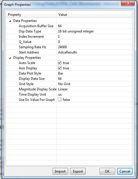
The first picture with sampling period 83.33 microsecond which what I got when I run the project and sampled my 2 kHz square wave input.

This picture when the sampling period is set to 41.665 microsecond, but when I run the program it shows the sampling period is 83.33 microsecond. If you look at the plotted adcresults, looks my 2 KHz input becomes 1 kHz. Honestly, I tried to solve it but I coudn't. One of the thing I tried is by changing the cpu clock from 200 MHz to 100 MHz in the cpu configuration register, but it didn't work .

For your information: I didn't change the system clock setting. hence I guess the pllsysclk is either 200 MHz or 100 MHz. I got IMULL = 20, FMULL= 0.0, SYSDIVSEL = 1 as in the picture below:

Thanks a lot for your support and help
Hayder