This thread has been locked.

If you have a related question, please click the "Ask a related question" button in the top right corner. The newly created question will be automatically linked to this question.

TMS320F28075: Interfacing MCP4921 DAC with tms320f28075 using SPI

Part Number: TMS320F28075

Hello,

i have to interface MCP4921 DAC chip with tms320f28075 using SPI bus. I am using SPIB module of controller for that purpose. I am using GPIO pins 22,23,24,25 as SPI pins. I have made required changes and those are reflected in the registers too . The problem is i am unable to see SPI clock on the pin .Please help .

  • Anvaya,

    Did you ensure ensure that the GPIO group mux is configured properly? For GPIO22, GPAGMUX2 =1, GPAMUX2 = 2.
    What hardware are you using? Is this a LaunchPad, ControlCard, or custom hardware? have you verified your HW is correct?
    Please see my recent response on this thread regarding SPI operation: e2e.ti.com/.../689215 have you attempted to transfer any data yet? The SPI will not toggle the Clock until a data transmission is occurring.

    Thanks,
    Mark
  • Hi Mark,

    Answers to your questions,

    1) Yes, the mux is getting configured properly. I have verified register status of both GPAMUX2 and GPGAMUX2.

    2) I am transferring a 16 bit data word after enabling the module. Mine is a custom hardware.

    I am using SPI in non-FIFO mode and only for transmitting data .

    And I am using chip select pin as normal GPIO pin and handling it through software only.

    Here is the code I am using to initialize and transmit the data. I have used functions provided in driverlib of C2000 ware for 28075 controller. Please let me know what I am missing something or is it the right way to generate clock and transmit data.

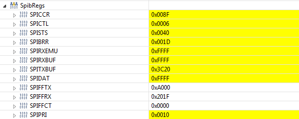
    I also want to know when does the SPIDAT register get loaded with SPITXBUF data. Because I observed that data comes in SPITXBUF but SPIDAT gets loaded with 0xffffffff.

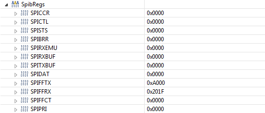
    I am also attaching snapshot of register status before and after run.

    void spiInitDAC()

    {

       /* Initialize device clock*/

       SysCtl_enablePeripheral(SYSCTL_PERIPH_CLK_SPIB);

       //clock    

       GPIO_setPinConfig(GPIO_22_SPICLKB);

       GPIO_setDirectionMode(22, GPIO_DIR_MODE_OUT);

       //SIMO

       GPIO_setPinConfig(GPIO_24_SPISIMOB);

       GPIO_setQualificationMode(24, GPIO_QUAL_ASYNC);

       //SOMI

       GPIO_setPinConfig(GPIO_25_SPISOMIB);

       GPIO_setPadConfig(25, GPIO_PIN_TYPE_PULLUP);

       GPIO_setQualificationMode(25, GPIO_QUAL_ASYNC);

       //chip select as GPIO pin only

       GPIO_setPadConfig(23, GPIO_PIN_TYPE_STD);

       GPIO_setDirectionMode(23, GPIO_DIR_MODE_OUT);

       GPIO_writePin(23,1);

       /* Must put SPI into reset before configuring it*/

       SPI_disableModule(SPIB_BASE);

       /*SPI configuration. Use a 1MHz SPICLK and 16-bit word size.*/

       SPI_setConfig(SPIB_BASE, DEVICE_LSPCLK_FREQ, SPI_PROT_POL0PHA0,

                     SPI_MODE_MASTER, 1000000, 16);

       /*Stop after 16 bit data transfer is complete*/

       SPI_setEmulationMode(SPIB_BASE, SPI_EMULATION_STOP_AFTER_TRANSMIT);

       /*Configuration complete. Enable the module.*/

       SPI_enableModule(SPIB_BASE);

    }

    void config_mcp4921()

    {

      uint16_t write_command = {0x3C20};

      GPIO_writePin(23,0);

      SPI_writeDataNonBlocking(SPIB_BASE,write_command);

      GPIO_writePin(23,1);

    }

    Befor Run

    After Run

    Thanks,

    Anvaya

  • Anvaya,

    Have you observed your procedure on an oscilloscope? The status of the registers after the run indicate that the transmission is complete and the value in the SPIDAT is what was actually received by the SPI.

    If you are able to remove the DAC chip and execute the procedure again, what is the behavior?

    -Mark
  • Thanks Mark for your help.