Hi,
I am new learner of 28335, now I want to use SPI of 28335 to interface with a DA chip. But it can't work well. the following is my program
#include "DSP28x_Project.h" // Device Headerfile and Examples Include File
// Prototype statements for functions found within this file.
// interrupt void ISRTimer2(void);
void spi_fifo_init(void);
void spi_init(void);
void main(void)
{
Uint16 sdata; // send data
InitSysCtrl();
InitSpiaGpio();
DINT;
InitPieCtrl();
IER = 0x0000;
IFR = 0x0000;
InitPieVectTable();
spi_fifo_init(); // Initialize the Spi FIFO
spi_init(); // init SPI
EALLOW;
GpioCtrlRegs.GPADIR.bit.GPIO19 = 1; // Configure outputs
GpioDataRegs.GPASET.bit.GPIO19=1;
EDIS;
sdata = 0x000F;
for(;;)
{
EALLOW;
GpioDataRegs.GPACLEAR.bit.GPIO19=1;
EDIS;
SpiaRegs.SPITXBUF=sdata;
// Wait until data is received
while(SpiaRegs.SPISTS.bit.INT_FLAG ==1)
{
EALLOW;
GpioDataRegs.GPASET.bit.GPIO19=1;
EDIS;
SpiaRegs.SPIRXBUF=SpiaRegs.SPIRXBUF;
}
}
}
// Step 7. Insert all local Interrupt Service Routines (ISRs) and functions here:
void spi_init()
{
SpiaRegs.SPICCR.all =0x000F; // Reset on, rising edge, 16-bit char bits
SpiaRegs.SPICTL.all =0x0006; // Enable master mode, normal phase,
// enable talk, and SPI int disabled.
SpiaRegs.SPIBRR =0x0004;
SpiaRegs.SPICCR.all =0x008F; // Relinquish SPI from Reset
SpiaRegs.SPIPRI.bit.FREE = 1; // Set so breakpoints don't disturb xmission
}
void spi_fifo_init()
{
// Initialize SPI FIFO registers
SpiaRegs.SPIFFTX.all=0xE040;
SpiaRegs.SPIFFRX.all=0x204f;
SpiaRegs.SPIFFCT.all=0x0;
}
I programmed it based on the tutorial SPI Loopback.I don't need interrupt and here I just want to sent a fix data to test it.
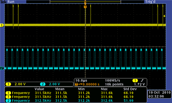
the question is I am not sure the pin the status of SPISTE pin should determined by the programmer or not. It is the reason why I changed the GPIO 19 status in program because I want to use this pin as the CS signal of the DA chip( when the data was transmitted, SPISTE is low and after the transmission is finished, the SPISTE is high). And I already defined the SPISTE as the GPIO in SpiaGpio function. And the SPISTE pin status changed but not right. So I am thinking is this term SpiaRegs.SPISTS.bit.INT_FLAG ==1 not right? Since I want to use this term to check if the tranmission is completed or not.
hope someone can help me or figure where is the problem.
thanks for the help


