Part Number: LAUNCHXL-F28069M
Tool/software: Code Composer Studio
Hello all,
24c04 eeprom datasheet is : 
The code I tested is below :
if (t<10)
            {
                 WriteEeprom(t, 10+t);
                 WriteEeprom(t+1, 10+t+1);

                 DataRead[t] = ReadEeprom(t);
                 //DataRead[t+1] = (ReadEeprom(t+1) << 8) | DataRead[t] ;
                 DataRead[t+1] = ReadEeprom(t+1) ;

                 t=t+2;
             }

             if (t>=10)
             {}
void I2CA_Init(void)
{
        I2caRegs.I2CMDR.all     = 0x0000;
       // Initialize I2C
       I2caRegs.I2CSAR = 0x0050;        // Slave address - EEPROM control code

       // I2CCLK = SYSCLK/(I2CPSC+1)

         I2caRegs.I2CPSC.all = 8;  //6     // Prescaler - need 7-12 Mhz on module clk


       I2caRegs.I2CCLKL = 10;           // NOTE: must be non zero
       I2caRegs.I2CCLKH = 5;            // NOTE: must be non zero
//     I2caRegs.I2CIER.all = 0x24;      // Enable SCD & ARDY interrupts

       I2caRegs.I2CMDR.all = 0x0020;    // Take I2C out of reset
                                        // Stop I2C when suspended

       I2caRegs.I2CFFTX.all = 0x6000;   // Enable FIFO mode and TXFIFO
       I2caRegs.I2CFFRX.all = 0x2040;   // Enable RXFIFO, clear RXFFINT,

   return;
}
Uint16 ReadEeprom(Uint16 e2promaddress)
{
    Uint16 addresslow;
         Uint16 addresshigh;


         I2caRegs.I2CMDR.bit.IRS = 1;                // reset I2C
         while (I2caRegs.I2CSTR.bit.BB == 1);        // busy loop
         I2caRegs.I2CSTR.bit.SCD = 1;                // Clear the SCD bit (stop condition bit)
         while(I2caRegs.I2CMDR.bit.STP == 1);        // stop bit loop

         addresshigh         = e2promaddress>>8;
         addresslow          = e2promaddress;
         I2caRegs.I2CSAR     = 0x0050;

         while (I2caRegs.I2CSTR.bit.BB == 1);
         I2caRegs.I2CMDR.all = 0x2620;               // start, no stop bit, master, tx, reset I2C
         I2caRegs.I2CCNT     = 0x0002;
         I2caRegs.I2CDXR     = addresshigh;
         I2caRegs.I2CDXR     = addresslow;
         while(!I2caRegs.I2CSTR.bit.ARDY);           // all ready?

         I2caRegs.I2CMDR.all = 0x2C20;               // start, stop bit when CNT =0, master, rx, reset I2C
         I2caRegs.I2CCNT     = 1;

         if(I2caRegs.I2CSTR.bit.NACK == 1)
         {
              I2caRegs.I2CSTR.all = I2C_CLR_NACK_BIT;    // 0x0002
         }
         I2caRegs.I2CMDR.bit.STP = 1;                    // stop bit when CNT=0

         while(!I2caRegs.I2CSTR.bit.SCD);                // stop bit detected?

         // tempdata  = I2caRegs.I2CDRR << 8;             // read data
         tempdata    = I2caRegs.I2CDRR;
         totalTemp = tempdata + totalTemp;

         DELAY_US(100);

    return(tempdata);
}
void WriteEeprom(Uint16 e2promaddress, Uint16 data)
{
    Uint16 addresslow;
         Uint16 addresshigh;
         Uint16 testval=3;
         I2caRegs.I2CMDR.bit.IRS = 1;            // reset I2C

         addresshigh         = (e2promaddress>>8)&0x00FF;
         addresslow          = e2promaddress&0x00FF;
         I2caRegs.I2CSAR     = 0x0050;           // EEPROM control bits + address (A0-A2). for 24LC256, 0 1 0 1 0 A0 A1 A2

         while (I2caRegs.I2CSTR.bit.BB == 1);

         I2caRegs.I2CCNT     = 3 ;
         I2caRegs.I2CMDR.all = 0x6E20;               //start, stop, no rm, reset i2c
         I2caRegs.I2CDXR     = addresshigh;
         I2caRegs.I2CDXR     = addresslow;

         //I2caRegs.I2CDXR     = (testval >> 8) & 0x00FF; // high byte data
         I2caRegs.I2CDXR     = testval;                 // low byte data
         wtempdata    = I2caRegs.I2CDXR;

         I2caRegs.I2CMDR.bit.STP = 1;                // stop bit when CNT=0

         while(!I2caRegs.I2CSTR.bit.SCD);            // stop bit detected?

         DELAY_US(5000);                             // 5ms = write cycle time of 24LC256 - based on datasheet 24LC256

    return;
}
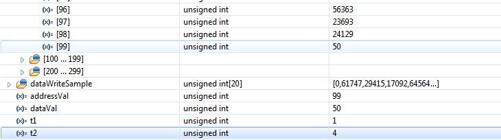
With these, first I wrote "3" value to 10 addresses (t<10). Then changed the code and wanted to read 20 addresses. All of them were "3". Then I wondered until which eeprom address, the value is "3" and it was 255 (t<256).
"totalTemp" below is 3*256 which means 256 of 24c04 addresses were defined as "3".

Is this a normal behavior? I am new about eeprom communication and I couldn't catch the reason.
Thank you.