This thread has been locked.

If you have a related question, please click the "Ask a related question" button in the top right corner. The newly created question will be automatically linked to this question.

TMS320F28377D: Qep Counter Reset

Part Number: TMS320F28377D
Other Parts Discussed in Thread: AM26LV32

Hello

I'm working on a BLDC motor control.

My board is very similar to the demo board with the ControlCard F28377

The software base from the exemple IDDK v2.0.

My feedback is the Qep + Hall.

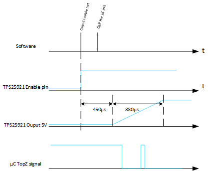
In a Calibration step, I get the number of Qep increment between the Electrical zero and the TopZ Event.

Then After that, the Qep is configured to Reset on TopZ event.  compute the Electrical angle by retreive this angle to obtain RawValue = 0 on the true electrical angle.

In a normal life, I get the  Hall captor and apply to the Qep Counter the position according the captor (+Angle Shift given by calibration step)

On the First Hall sensor change value, I make the same because now, we sure we are exactly on the transition of two hall combination.

Then on the TopZ event, the Qep counter is set to 0 and then now, I'm exactly on the good position.

This work correctly, BUT sometime, between the Hal Captor rising edge and the TopZ, I see the QepCnt reset to 0 without any reason! (No Top Z FLG.IEL = 0)

I'm using the QEP computation given on the IDDK exemple, the flag IndexSyncFlag is not set.

What could be Reset the QEP counter excepted the TopZ in my case???

The Qep Config is following:

/*-----------------------------------------------------------------------------
    Initialization states for EQEP Decode Control Register
------------------------------------------------------------------------------*/
#define DV_QEP_QDECCTL_INIT_STATE     ( XCR_X2 + QSRC_QUAD_MODE )

/*-----------------------------------------------------------------------------
    Initialization states for EQEP Control Register
------------------------------------------------------------------------------*/
#define DV_QEP_QEPCTL_INIT_STATE      ( QEP_EMULATION_FREE + \
                                        PCRM_INDEX + \
                                        0 + \
                                        IEL_RISING + \
                                        QPEN_ENABLE + \
                                        QCLM_TIME_OUT + \
                                        /*UTE_ENABLE*/0 )

/*-----------------------------------------------------------------------------
    Initialization states for EQEP Position-Compare Control Register
------------------------------------------------------------------------------*/
#define DV_QEP_QPOSCTL_INIT_STATE      PCE_DISABLE

/*-----------------------------------------------------------------------------
    Initialization states for EQEP Capture Control Register
------------------------------------------------------------------------------*/
#define DV_QEP_QCAPCTL_INIT_STATE     ( UPPS_X32 + \
                                        CCPS_X128 + \
                                        CEN_ENABLE )

The computation of the Electrical angle is following:

{                                                                                 \
  float32 ElecThetaTemp;                                                          \
  /* Check the rotational direction */                                            \
  IF_MotorPosition_iQep.DirectionQep = (*DV_Qep_Regs[2]).QEPSTS.bit.QDF;                              \
                                                                                  \
  /* Check the position counter for EQEP1 */                                      \
  IF_MotorPosition_iQep.RawTheta = (*DV_Qep_Regs[2]).QPOSCNT - IF_MotorPosition_iQep.InitTheta;                           \
                                                                                  \
  if (IF_MotorPosition_iQep.RawTheta < 0)                                                             \
    IF_MotorPosition_iQep.RawTheta = IF_MotorPosition_iQep.RawTheta + (*DV_Qep_Regs[2]).QPOSMAX + 1;                      \
  else if (IF_MotorPosition_iQep.RawTheta > (*DV_Qep_Regs[2]).QPOSMAX)                                \
    IF_MotorPosition_iQep.RawTheta = IF_MotorPosition_iQep.RawTheta - (*DV_Qep_Regs[2]).QPOSMAX - 1;                      \
                                                                                  \
  /* Compute the mechanical angle */                                              \
  IF_MotorPosition_iQep.MechTheta= IF_MotorPosition_iQep.MechScaler*IF_MotorPosition_iQep.RawTheta;                                           \
  /* Compute the electrical angle  */                                             \
  ElecThetaTemp = IF_MotorPosition_iQep.PolePairs*IF_MotorPosition_iQep.MechTheta;                                        \
  IF_MotorPosition_iQep.ElecTheta = (ElecThetaTemp) -floor(ElecThetaTemp);                            \
                                                                                  \
  /* Check an index occurrence*/                                                  \
  if (((*DV_Qep_Regs[2]).QFLG.bit.IEL == 1))                                                      \
  {                                                                               \
    IF_MotorPosition_iQep.IndexSyncFlag = 0x00F0;                                                     \
    IF_MotorPosition_iQep.QepCountIndex = (*DV_Qep_Regs[2]).QPOSILAT;                                 \
    ((*DV_Qep_Regs[2]).QCLR.bit.IEL = 1);  /* Clear interrupt flag */                         \
  }                                                                               \
                                                                                  \
  /* Check unit Time out-event for speed calculation: */                          \
  /* Unit Timer is configured for 100Hz in INIT function*/                        \
  if((*DV_Qep_Regs[2]).QFLG.bit.UTO == 1)                                         \
  {                                                                               \
    /***** Low Speed Calculation   ****/                                          \
    if(((*DV_Qep_Regs[2]).QEPSTS.bit.COEF || (*DV_Qep_Regs[2]).QEPSTS.bit.CDEF))  \
    { /* Capture Counter overflowed, hence do no compute speed*/                  \
      (*DV_Qep_Regs[2]).QEPSTS.all = 0x000C;                                      \
    }                                                                             \
    else if((*DV_Qep_Regs[2]).QCPRDLAT!=0xffff)                                   \
      /* Compute lowspeed using capture counter value*/                           \
      IF_MotorPosition_iQep.QepPeriod = (*DV_Qep_Regs[2]).QCPRDLAT;                                   \
  }                                                                               \
}

This comes only before the TRUE real TopZ signal. Never after.

Thank for your help.


  • Hi,

    "This work correctly, BUT sometime, between the Hal Captor rising edge and the TopZ, I see the QepCnt reset to 0 without any reason! (No Top Z FLG.IEL = 0)"

    Did you mean Index pulse by TopZ event? Can you check if there is any noise on the QEP inputs?
    Have you configured GPIO filters to filter out any possible noise in the system? This should rule out if the counter is getting reset due to noise on the inputs.
    Also, is the reset happening consistently under certain condition or is it random instance every time?
    When the qepcnt is not reset, are the counter values changing as expected? Does the position inferred match with the expected position?

    -Bharathi.

  • The QEP like showing by provided init code is configured to count on A and B event.

    The QEPMax is 9999 (Coder is 2500 pulse / lap)

    Also, it is configured to reset the count on Index Pulse (TopZ).

    Then I see the Qep reset to 0 without any reason, with random behavior but always before reach the real FIRST index pulse.

    Then by some tracing method, I confirm the flag FLG.IEL was not set when this "dummy" Reset occurs.

    This indicate no noise into Index pin because if it was the case, this flag will be set!

    But I checked the hardware signal. The scope was no trig an edge, then no noise...

    No filter is configured on GPIO. I think this is not necessary to keep a good reactivity.

    When the counter is no reset, the counter value change as expected without any problem. Just sometime this counter reset before reach the TopZ.

    If problem not occurs before the first real topZ, the problem never occurs after. (until today... maybe tomorow it will! :-)

    Thank

  • Hi,

    So the reset occurs only in the initial stage - before the occurrence of the first index pulse.
    Is there any specific count value at which the reset occurs?
    Is the counter counting as expected before/after the spurious reset?
    Is there any specific portion of your s/w code execution during which the reset occurs?
    It's certainly not expected behavior and since you said it's occurring randomly, makes it difficult to pinpoint the problem.

    -Bharathi.
  • Hello

    I made some observation.

    In fact, the QEP motor output are differential signals (A, B and Z)

    On the board, these differential input are transformed via the AM26LV32 (Low voltage High Speed quadruple differential Line receiver).

    On other part, the QEP coder power is not directly the 5V power, but pass by a power management (TPS25921: 4.5V - 18V eFuse with Precise Current Limit and Over Voltage Protection)

    The µC manage on output an Enable signal which enable the TPS25921 to power the codeur. The 5V output power the Qep but also enable the output of AM26LV32 via the "Active-High Select pin)

    The software, on the init phase realize the following operation:

    - Set Enable Output

    -... Make some other initialisation (Without relationship with QEP)

    - Initialise the QEP module hardware.

    But the reaction time of the TPS25921 is like following:

    - Time between Enable Input Pin and start of increase voltage on output : 450µs

    - Time of the power up ramp to reach 5V : 880µs => this is signal which enable the AM26LV32.

    This result the following:

    As you can see, during the QEP codeur initialisation, the TopZ input is High. And then after it, we have a Top Z signal due to power establish into the Qep and the activation of the AM26LV32.

    Then on the begin of the management, I seen the TopZ index flag was set, then A clear it. But it seems this produce the problem because when the QEP begin to move (few  A and B edge), the Counter Reset like if it memorized the previous TopZ signal and apply it later…??

    With this behavior, problem was occurs after 11 try, and then after 4 try.

    Then, I test by link the Enable Pin of TPS25921 to permanant 3.3V to power on the Qep very before QEP Hw initialisation.

    After 35 try, problem was not reproduced.

    So this could confirm the problem come from this. But Without explain why and without fin a solution. I need to can Enable or disable the Qep power during the life of the product and during the board is ON without need to Power Off/On the board.

    Then I must find a software solution which is not disturbed by this TopZ glitch.

    I try to Disable/Enable QEP module without success. (QEPCTL.QPEN)

  • Hi,

    I agree that this glitch could cause unpredictable behavior in the eQEP module.
    Note the timing requirements of inputs in the device data sheet section "eQEP Timing Requirements".
    Like I said earlier I would still suggest to have GPIO filter configured to filter out such glitches.
    With that your issue of dynamically reset of "Enable or disable the Qep power during the life of the product" will also be addressed.

    "I try to Disable/Enable QEP module without success. (QEPCTL.QPEN)"
    QPEN will not bring the system to completely reset state - you can use peripheral software reset to do this.
    Write to corresponding eQEP module in SOFTPRES4 register.

    -Bharathi.

  • I will test the SOFTPRES4 and come back here to inform you.
    Thank
  • Hello
    After test, this is not better! :

    I made the following test:
    By a stub code, a execute a QEP reset by set and clear SOFTPRES4.
    After that, I set the QEP register with its init value.
    Then I set the CNT to the value saved before the QEP reset
    Then I clear IEL flag because it is always set after the QEP reset while the Datasheet indicate Reset value = 0 (???...)

    Then, I move the axis, on the first motor move (first QEP A / B rising) teh QEPCNT return always to 0!
    :-(
  • This work now.
    In fact, we must call EALLOW before modify SOFTPRE4 register...
  • That's great! Yes - it's an EALLOW protected register.