This thread has been locked.

If you have a related question, please click the "Ask a related question" button in the top right corner. The newly created question will be automatically linked to this question.

TMS320F28377D: I have a question about the PLL setting of the TMS320F28377D chip.

Part Number: TMS320F28377D
Other Parts Discussed in Thread: C2000WARE

Hi,

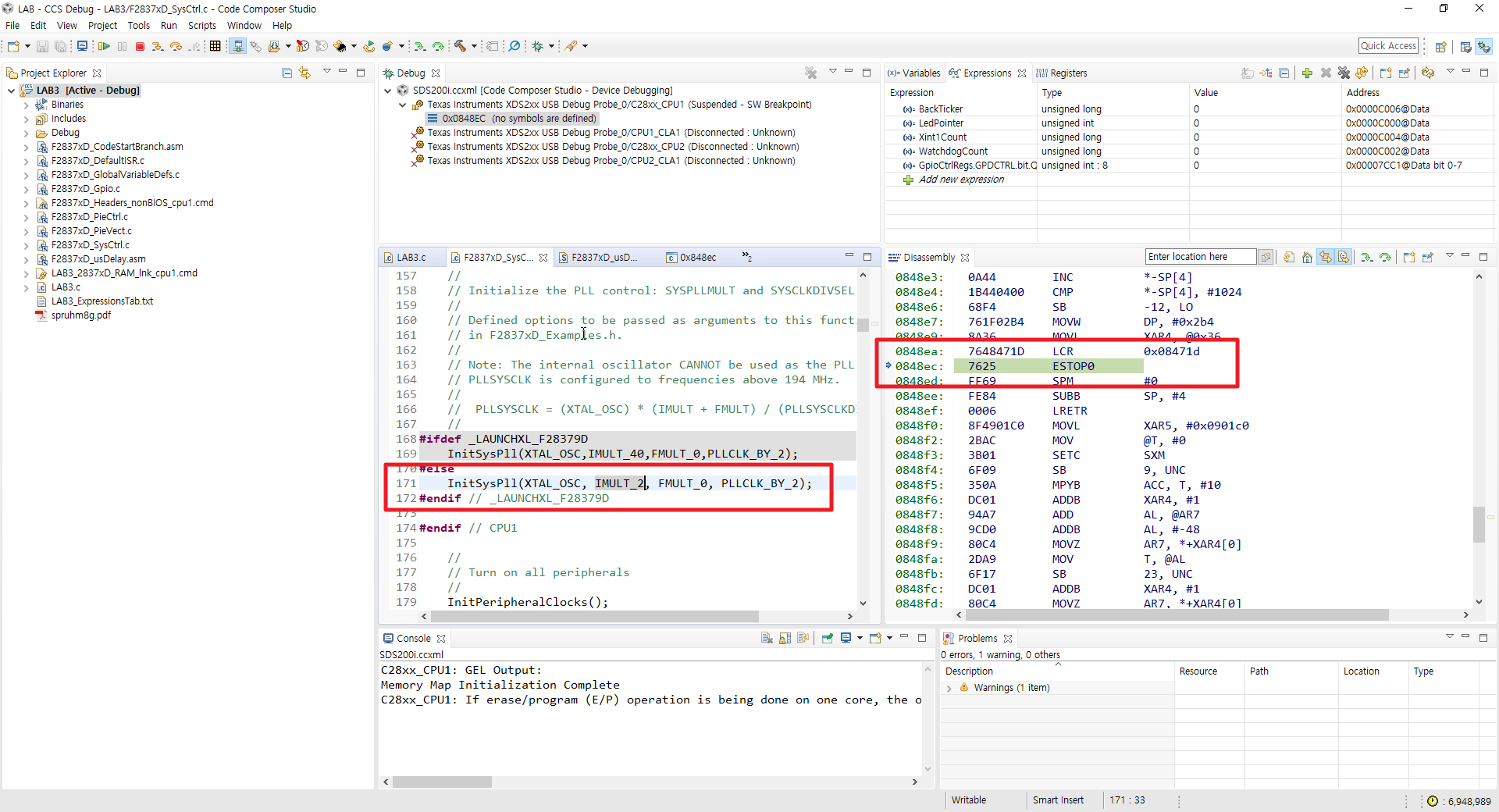
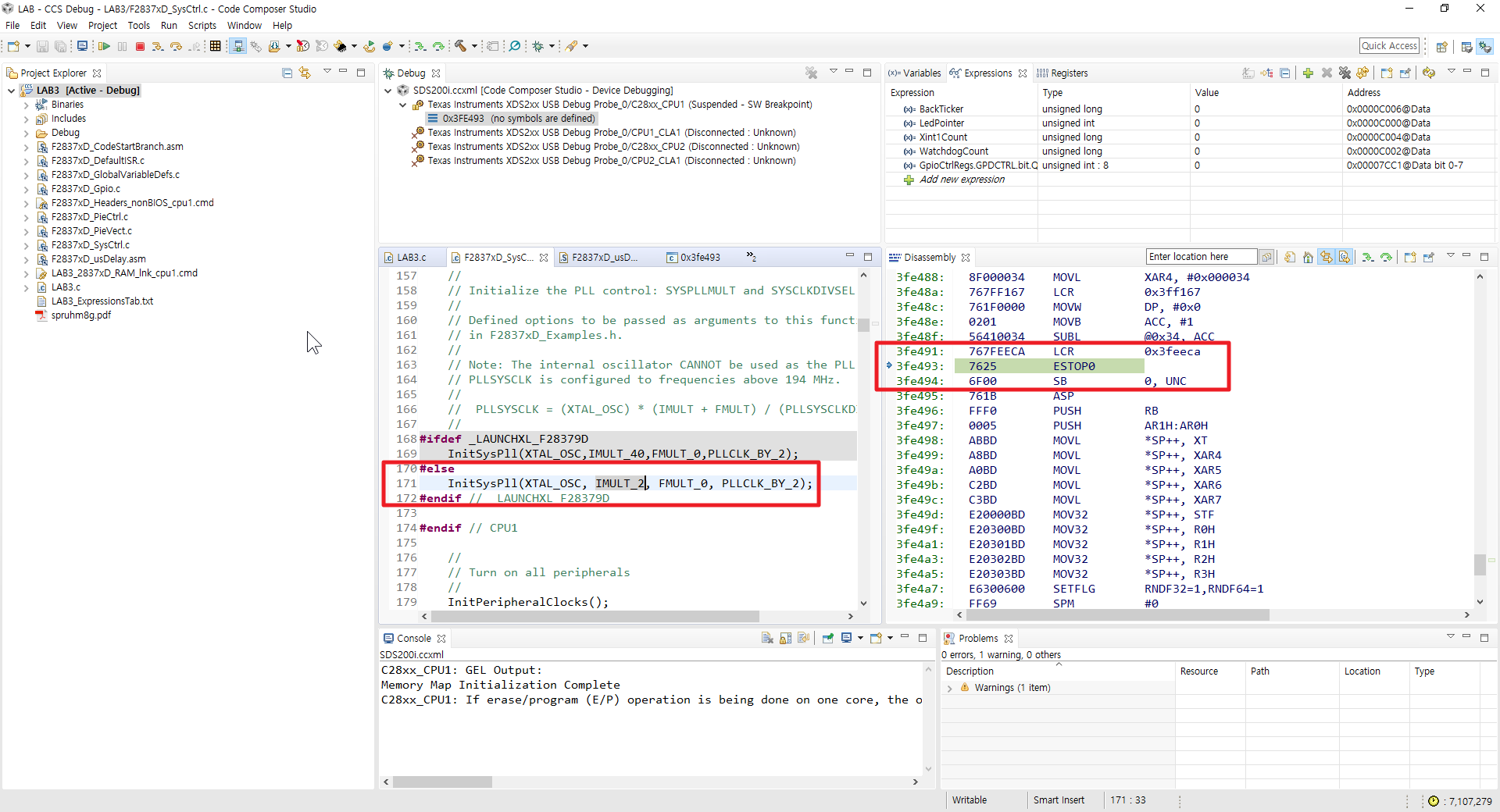
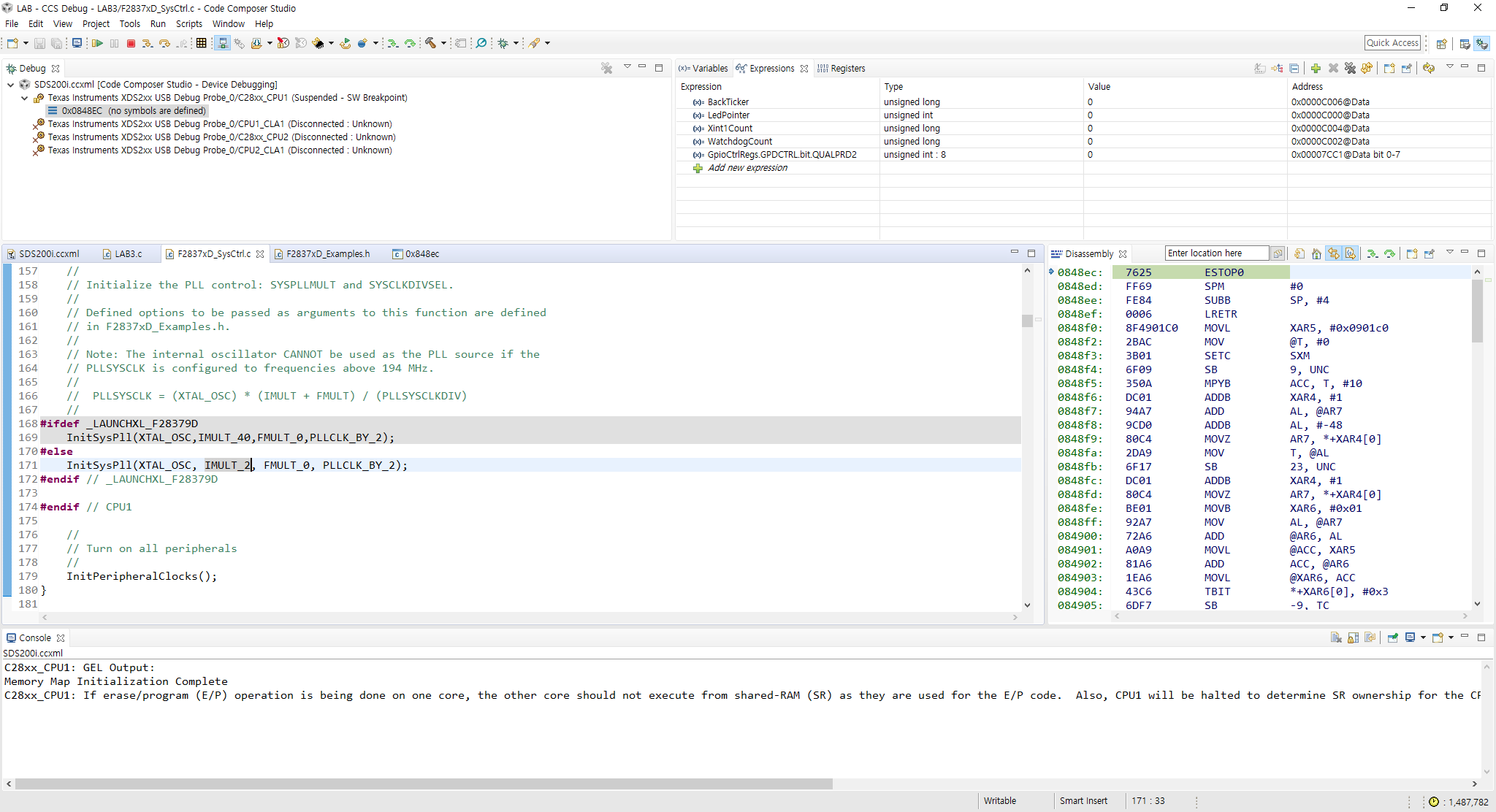
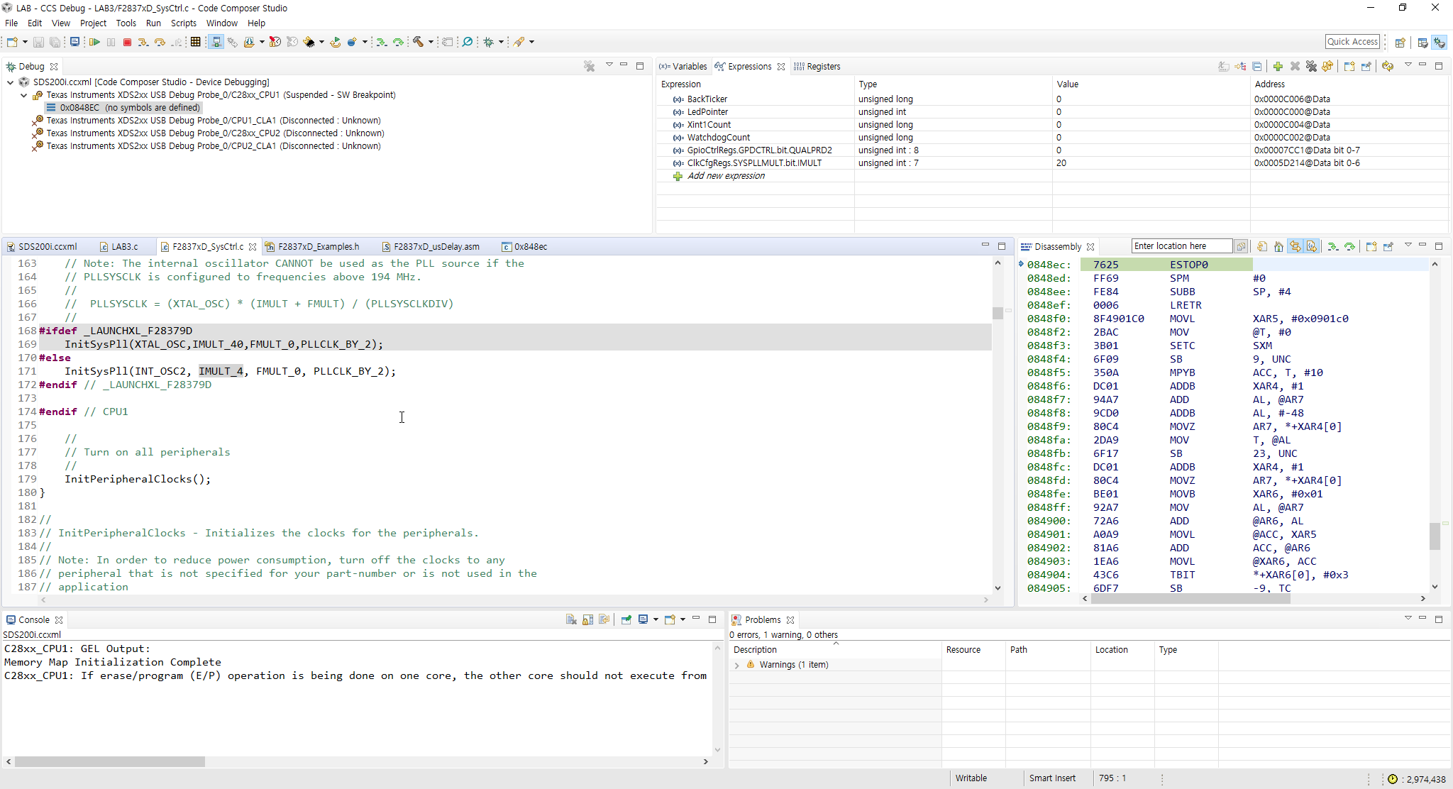
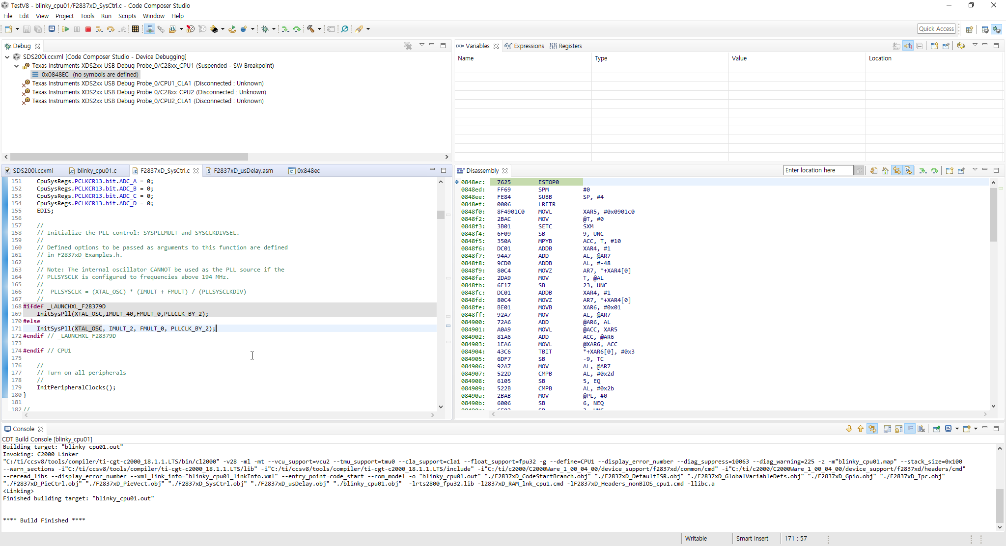
For testing the TMS320F28377D chip PLL circuit, I changed the argument of InitSysPll( ) function from IMULT_20 to IMULT_2 to lower the CPU clock frequency to 20MHz, and run it after rebuild the program.

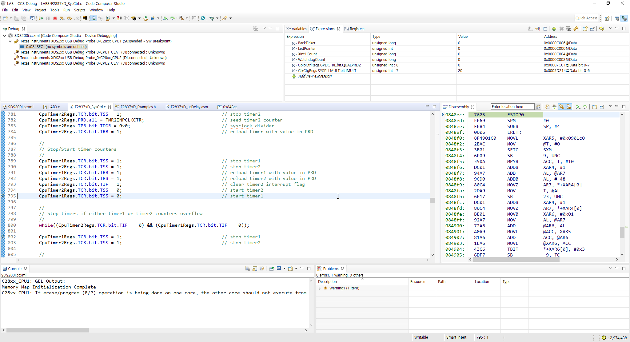
However, the main( ) function is not executed and PC halt in the ESTOP0 code at address 0x003FE493 as shown in the attached image.

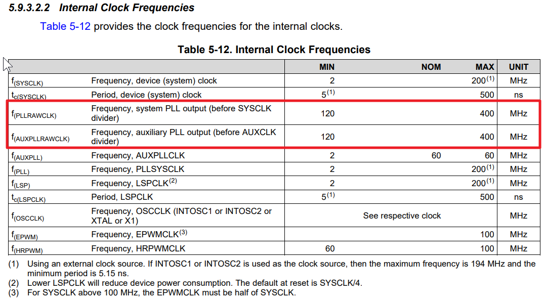
Same problem occurs at other frequency settings, such as 10MHz & 5MHz, but does not cause problems at higher CPU clock frequencies, such as 100MHz.

I wonder if this problem is likely to be caused by the pull-up resistance and bypass capacitor value of the / XRS pin. (I currently use a 16kohm resistor and a 100nF capacitor.)

If it is caused by other causes, I want to know about it specifically.

Thanks in advance.

  • Hi ,

    Can you tell me what is the clock_source ?
    void InitSysPll(Uint16 clock_source, Uint16 imult, Uint16 fmult, Uint16 divsel)
    Is it XTAL ? what is the frequency ?
    Which board are you testing it on ?
    Which example are you using ?

    I don't see an attachment.

    Please refer section 2.7.6 Clock Source and PLL Setup of the TRM for details on right clock configurations.
    www.ti.com/.../spruhm8g.pdf


    Regards.
  • I am using 20MHz crystal outside the TMS320F28377D chip.
    The attachment image is missing in the previous question. So when I try to capture again, the address at which the program counter stops is changed at each execution.

  • hi ,

    Its not just the address but even the code generated seems to be different ... 

    Can you "step into" the code and tell me when exactly it got to the ESTOP ?

    Which board are you testing it on ?  Control card ?

    Can you try using the INT_OSC as the clock source ?

    Regards.

  • Attached the captured image.

    Could the cause of the problem be the CPU_RATE definition in the F2837xD_Examples.h header file?

  • Program run normally till the line number 795 of the F2837xD_SysCtrl.c file.

    However, if you run the program again, the breakpoint on line number 802 will not be reached and will stop at the strange address ESTOP0 code.

  • hi ,

    The CPU_RATE is used for the macro DELAY_US(x) . Unless we are using this in the example it should be of our concern.
    From the snippet , it seems that the issue is with the CPUtimer2 not overflowing or reaching 0 to test the correctness of the PLL clock generated on PLL locking .
    So the issue does seem to be with the clock settings .

    Which board are you testing it on ? Control card ? This way we are sure of the freq etc...

    Can you try using the INT_OSC as the clock source ?
  • Hi,

    I have tried the same test as above using INT_OSC2, but the result is the same.

  • And Which board are you testing it on ? Control card ? This way we are sure of the freq etc...
  • I use my own processor module rather than TI's ControlCARD.

    This processor module uses the TMS320F28377DZWTT Rev.C.

  • hi ,

    Could you check the below recent example in the c2000ware (www.ti.com/.../C2000WARE) and tell me if the issue persists ?
    c2000ware\device_support\f2837xd\examples\cpu1\blinky\cpu01
    or
    c2000ware\driverlib\f2837xd\examples\cpu1\led

    I want to make sure its not in a software configuration ...since the INT_OSC2 also seems to have a problem.

    if it still has issues then its could be a hardware issue. Please check if crystal and the rest of the hardware is correct and up.

    Regards.
  • Okay. I will test the changing the PLL configuration with the example you just mentioned. and then I will leave a comment again as soon as the results are confirmed.
  • Hi,

    I tried running the 'blinky' example included in C2000Ware as you told me, but the same problem is observed.

  • I wonder if the cause of the question is related to the attached images.

    In the 'F2837xD_Examples.h' header file, 'CPU_RATE' is defined only down to 120 MHz, and the minimum value of 'PLL output clock frequency' is defined 120MHz in the datasheet.

  • hi ,

    Since the blinky example is having issues, this is surely a hardware play.

    Good catch ! i think this could be a limitation of the PLL in the device .
    I should get this note or disclaimer added to the comments above the API.

    In that case , do you see it work fine from 120Mhz to 200Mhz setting for the PLL?
    InitSysPll(XTAL_OSC,IMULT_40,FMULT_0,PLLCLK_BY_2); by manipulating only the 1st 3 arguments ...

    Note: The internal oscillator CANNOT be used as the PLL source if the PLLSYSCLK is configured to frequencies above 194 MHz.

    Regards.
  • Hi,

    The following tests used the TMS320F28377DZWTT (Rev.C) chip and the blinky_dc example from the TI C2000Ware.

    InitSysPll(INT_OSC2, IMULT_4, FMULT_0, PLLCLK_BY_1); -----> 10MHz Internal OSC 2 / 40MHz / Work
    InitSysPll(INT_OSC2, IMULT_3, FMULT_0, PLLCLK_BY_1); -----> 10MHz Internal OSC 2 / 30MHz / not Work (ESTOP0 at 0848ec)

    InitSysPll(INT_OSC2, IMULT_8, FMULT_0, PLLCLK_BY_2); -----> 10MHz Internal OSC 2 / 40MHz / Work
    InitSysPll(INT_OSC2, IMULT_7, FMULT_0, PLLCLK_BY_2); -----> 10MHz Internal OSC 2 / 35MHz / not Work (ESTOP0 at 0848ec)

    InitSysPll(XTAL_OSC, IMULT_4, FMULT_0, PLLCLK_BY_1); -----> 20MHz External Crystal / 80MHz / Work
    InitSysPll(XTAL_OSC, IMULT_3, FMULT_0, PLLCLK_BY_1); -----> 20MHz External Crystal / 60MHz / not Work (ESTOP0 at 0848ec)

    InitSysPll(XTAL_OSC, IMULT_8, FMULT_0, PLLCLK_BY_2); -----> 20MHz External Crystal / 80MHz / Work
    InitSysPll(XTAL_OSC, IMULT_7, FMULT_0, PLLCLK_BY_2); -----> 20MHz External Crystal / 70MHz / not Work (ESTOP0 at 0848ec)

    In general, most developers will use the maximum clock frequency supported by the chip. However, in some cases it may be necessary to operate at a lower clock frequency. What I want to know is the minimum clock frequency that can be set through the PLL circuit of the TMS320F2837x processor. According to the datasheet it says that 'f(SYSCLK)' can be set from a minimum of 2MHz up to a maximum of 200MHz, but in fact it does not seem to be.

    Thanks in advance.
  • hi Nam

    Since the datasheet specifies to use the 120Mhz to 400 Mhz before the divider , i would suggest to check for only these options .
    If the "f(SYSCLK)' can be set from a minimum of 2MHz up to a maximum of 200MHz" , its because of the multiplier within the PLL and divider using the SYSCLK divider . But the PLL output before the SYSCLK divider should be in the range suggested by the datasheet.

    Regards.
  • Sorry for the delay. Your answer was a great help. Thank you.