This thread has been locked.

If you have a related question, please click the "Ask a related question" button in the top right corner. The newly created question will be automatically linked to this question.

CCS/TMS320F280049: CAN not working at High Baud Rate

Part Number: TMS320F280049
Other Parts Discussed in Thread: ISO1050

Tool/software: Code Composer Studio

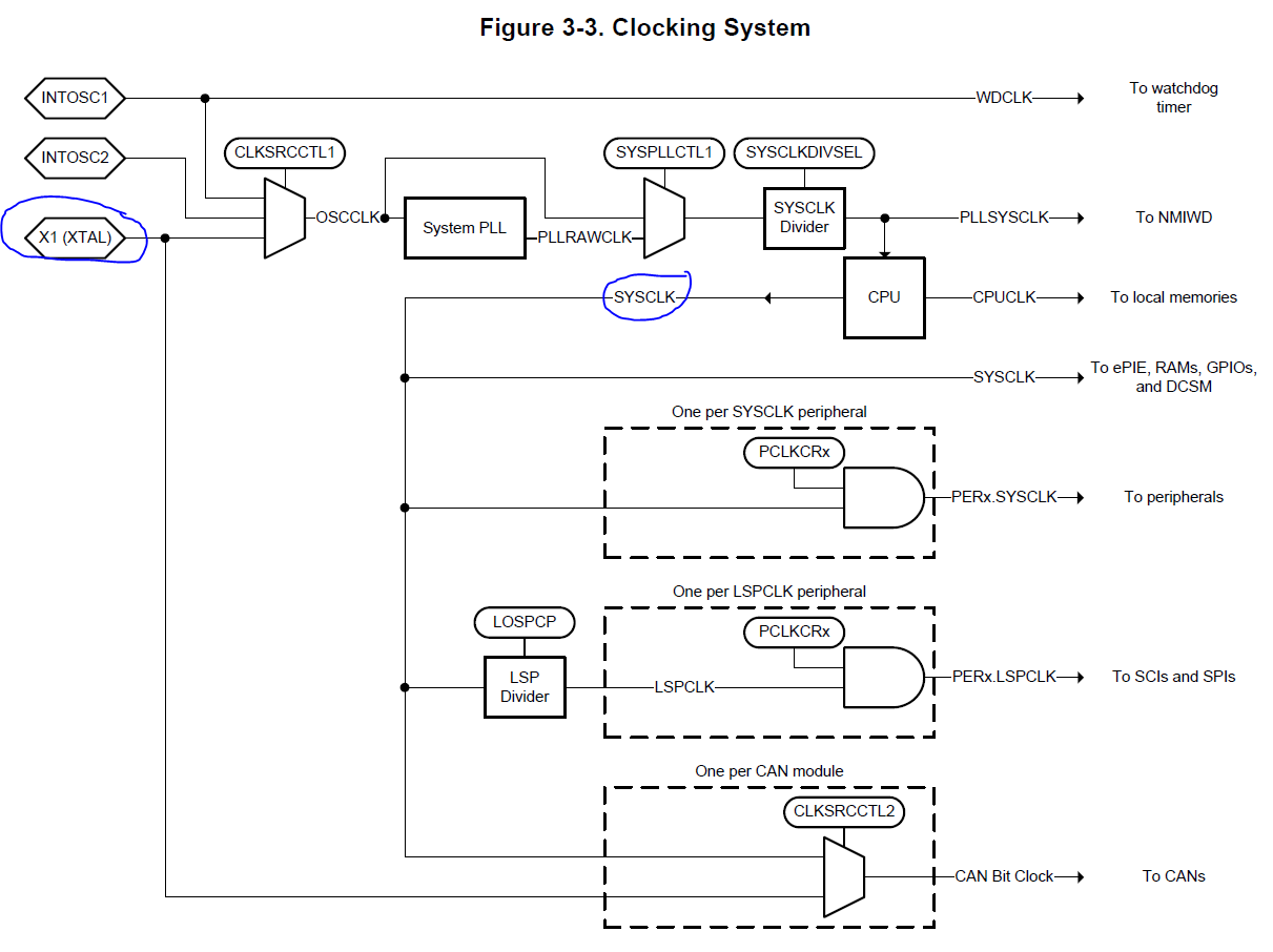
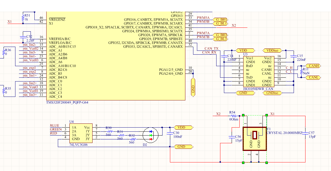
We have our clock setup the same as TI's Clocking Circuitry in MCU009A(001)_Sch. Our External Oscillator is not exactly the same but has the same Frequency Stability of 10 ppm. We are using the ISO1050 CAN transceiver. We are reading the CAN messages using two different software, BUSMASTER and PCAN-View via a PEAK USB Connection to the computer. We are running TI's example code can_ex3_external_transmit. BUSMASTER shows errors and  PCAN-View does not show any messages. If we lower the Baud Rate from 500k to 250k or 50k, everything works fine. We have a 120 ohm termination resistor between CANH and CANL. This is R11 in our schematic below, even though it is marked Do Not Populate. Also R51 which was used for the internal clock source has been removed. 

Thank you in advance for your assistance.

Ian

  • Ian,

                It appears there is a termination issue. Could you please provide the following:


    A sketch of your CAN bus that clearly shows the number of nodes and the position of the termination resistors. (Hand drawn is OK)


    An oscilloscope capture of the waveform at the CANRX pin of F280049.

  • It is conceivable your bit-timing parameters are not correct. Please download SPRAC35 and figure out the correct parameters fro your network.

  • Ian,

       Thank you for closing the post. Would you mind sharing what was wrong, for the benefit of others?

  • I had to make one change to TI's example code can_ex3_external_transmit. Using the CAN Bit Timing Calculator provided by TI, we saw that Bit Time at the bottom of the following screenshot was 20.

    So we changed 

    CAN_setBitRate(CANA_BASE, DEVICE_SYSCLK_FREQ, 500000, 16);

    to

    CAN_setBitRate(CANA_BASE, DEVICE_OSCSRC_FREQ, 500000, 20);

    You can also see that we changed the chosen clock to have it no become more loose by going through PLL.

    This is what we had to do to get the code to work at 500 kBaud. I can see how the code worked for TI since both CANA and CANB were set the same way. 
    CAN_setBitRate(CANA_BASE, DEVICE_SYSCLK_FREQ, 500000, 16); and 
    CAN_setBitRate(CANB_BASE, DEVICE_SYSCLK_FREQ, 500000, 16); 

    Since they were set the same they could read each others messages. However if you use a software to read the messages like BUSMASTER, MATLAB, or PCAN-View, it would not work. We were intercepting the messages with these different programs. 


    Thanks

    Ian

  • Could you please provide the value of X1 & SYSCLK and also the value of CAN_BTR before/after you fixed the problem?
  • 100 MHz SYSCLK CAN_setBitRate(CANA_BASE, DEVICE_SYSCLK_FREQ, 500000, 16); 100

    BRP =  11;

    BRPE = 0;

    SJW = 3;

    TSEG1 = 8;

    TSEG2 = 5;

    20 MHz X1 CAN_setBitRate(CANA_BASE, DEVICE_OSCSRC_FREQ, 500000, 20); 

    BRP =  1;

    BRPE = 0;

    SJW = 3;

    TSEG1 = 10;

    TSEG2 = 7;