This thread has been locked.

If you have a related question, please click the "Ask a related question" button in the top right corner. The newly created question will be automatically linked to this question.

TMS320F28027: Question about positive/negative current feedback within instaspin-foc&motion user guide

Part Number: TMS320F28027

Dear Champs,

I asked about this question is because my background is firmware/software design, and not good at hardware design.

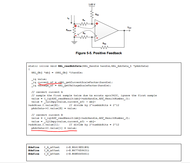
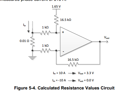
The instaspin-foc&motion user guide mentioned about positive/negative current feedback, it has relationship that 3.3V --> 10A, 0V--> -10A, and the equation is vout = 1.65 + 16.5*0.01*I . What I understand about this circuit is that higher current will have higher volts on ADC pin(larger adc result), and vise versa.

 But the below code for this positive feedback shows offset and current_sf are negative. That means the value of pAdcData->I.value[1] is negative when the current is 10A, so I'm confused about this, can you please help to give more detail explanation?

  • The section above this diagram explains the sign inversion. The positive feedback requires polarity inversion because of the layout of the op-amp in the circuit you have shown (note the layout of the inverting and non-inverting terminals)

    Sean
  • Hi Sean,

    Regarding to the positive feedback current sense circuit, what the relationship between vout and I is that

    vout = 1.65 + 16.5*0.01*I, then I = (vout - 1.65)*100/16.5, and the adc result relations is that,

    I = (adc_result-offset)*K, I = adc_result*K - offset*K, where K and offset are positive, but the equation shows in the user guide is that

    pAdcData->I.value[1] = _IQ12mpy(value,current_sf)  -  obj->adcBias.I.value[1];  where current_sf(K) and adcBias(offset) are negative.


    Can you please help me understand why does the sign of current in code is different with circuit?

  • Hey Sean,

    May I get more comment from you?
  • The current offset value includes the sign and gain also in this code. The equation of the differential amplifier is Vout=(Vpos-Vneg)*G+Vref for both positive feedback and negative feedback in instaSPIN user's guide. But, the (Vpos-Vneg) = I*Rs for negative feedback and (Vpos-Vneg) = -I*Rs for positive feedback since sampling freewheel current in the inverter. For the positive feedback you mentioned above, the derivation process is as below
    -I*Rs=(Vout-Vref)/G
    I*Rs = -Vout/G + Vref/G
    I*Rs = -Vou/G - (-Vref/G)
    (-Vref/G) will be set to obj->adcBias.I.value[0], so it's a negative value for positive feedback. You might find a more detailed description in some motor control papers that could be searched in TI website.

  • Hi Yanming,

    Thanks for the detail derivation. Can you please recommend a ti paper which describe about this?
  • Hi Yanming,

    May I get further update about this?
  • You might find many application notes about amplifier knowledge on TI website, which have a very detailed description about these content. Like “Analog Engineer’s Pocket Reference Guide 4th Edition (Rev. B) (slyw038b)“, “HANDBOOK OF OPERATIONAL AMPLIFIER APPLICATIONS (sboa092b)”…..
  • Thanks for your great support.