This thread has been locked.

If you have a related question, please click the "Ask a related question" button in the top right corner. The newly created question will be automatically linked to this question.

TMS320F28052F: Serial Flash Programmer and Autobaud Lock

Part Number: TMS320F28052F
Other Parts Discussed in Thread: CONTROLSUITE, C2000WARE

I am attempting to utilize TI's serial_flash_programmer utility found within controlSUITE to apply a firmware update to my MCU while in SCI bootmode. However, I have been unable to establish a connection between my PC and the MCU.

I bring pins 58 and 9 low and leave pin 74 high to establish the MCU's SCI boot mode. I've power-reset the board and connected the MCU through pins 48 and 49 to an RS-232 connection which goes to a COM port on my PC. The following is my implementation of the utility, and said utility hangs on the f05_DownloadImage step for over an hour. 

Both .txt files have been made as a post build step in CCS: "${CG_TOOL_HEX}" "${BuildArtifactFileName}" -boot -sci8 -a -o "${BuildArtifactFileBaseName}.txt"

When serial_flash_programmer is called, I receive one flash on an Rxd LED, confirming that at least one thing (which I assume is the autobaud lock character) is being sent from the PC to the device. There is no indication that the device ever transmits anything back to the PC.  

I did go back into CCS and modify the kernel provided under controlSUITE from the default f28055 target to the appropriate f28052f. 

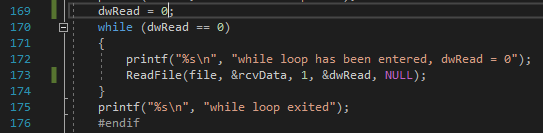
I have also attempted debugging this implementation through Visual Studio and the program continues to hang at the same spot. I believe it may be due to a failure in receiving a confirmation of autobaud locking as I have included multiple print statements and believe the code stays in the following while loop: 

However, I have also run ModScan on the device using the same setup (minus bringing pin 58 low so as to boot normally), and have been successful at obtaining a connection at multiple baud rates above and below the default 9600. 

My device is unlocked and does not have set CSM keys. 

I have also attempted to follow the scia_loopback example in CCS while in SCI bootmode, but am never able to complete debugging because of the following error code: 

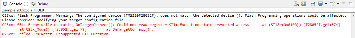
Is there anything that I'm obviously doing incorrectly? Why does my device not seem to want to connect/autobaud when the pins are set for SCI boot? 

Thanks for any insight!

  • Hi,

    First of all, thank you for the very verbose explanation of the issue. Second, thank you for taking such steps to resolve the issue. Your debugging efforts are commendable.

    It appears, like you have said, that the autobaud is not working. You can try to accomplish this first by simply opening a COM port from a terminal like Putty. To test that you are properly booting to SCI boot mode and have the right connections, just open a COM port and send an 'A' or 'a'. You should see an 'A' or 'a' back on the terminal.

    You can also load the boot rom symbols and see if it is properly booting to SCI boot mode.

    Let me know what you find.

    Regards,
    sal
  • Thank you for getting back to me so quickly, Sal.

    I attempted to use Putty to establish a connection and sent multiple 'A' and 'a' signals to the board. These signals were indicated as being received as I could see the Rxd LED light up each time I sent a message.

    Nothing was sent back from the MCU (Txd LED remained unlit), and the terminal remained blank.

    Could you elaborate on what you mean/the procedure for " load the boot rom symbols and see if it is properly booting to SCI boot mode?"

    Thanks
  • After connecting to the target C28x, in your Debug view, you can click on RUN->Load Program->Add Symbols. THhen point to the .out file for the bootrom in C2000Ware. C2000Ware/libraries/bootrom/[device]

    You may then have to locate file from CCS. A Locate File button may appear in the text editor. Then point it to the /source directory of the bootrom.

    It appears you are not receiving back the 'A'. This may be because there is something wrong with the TX pin connection, or the device is not properly receiving an 'A' and there is something from with the Rx pin connection to the device.

    Hope this helps.

    sal
  • I am currently scoping my device at different areas along the datapath to try determining if there is a loss of a connection at the Tx or Rx pin.

    On another note though, I did not find a .out file under C2000Ware_1_00_04_00/libraries/boot_rom/f2805x. There are only .lib files present.
  • Hi,

    You can try the .lib files. But it looks like we may not have released the symbols for the entire boot ROM for that device.

    sal
  • Hello,

    While in SCI bootmode, I have confirmed that the transmitted 'A' from Putty reaches pin 49 (Rx) of the MCU. There is no response at pin 46 (Tx). When in normal bootmode, I am able to communicate with the MCU in ModScan through the same pins, so I do not think it is a connection problem.

    Do I have to add any libraries to the source code or reprogram the MCU for it to work? It seems the 'A' is reaching the MCU when in SCI bootmode. Or could the SCI Bootmode be reassigning pins in such a way that pins 48/49 are no longer Tx/Rx?

    Thanks
  • HI James,

    The SCI boot loader on f2805x uses pins 28/29.

    Please see the TRM SPRUHE5

    www.ti.com/lit/spruhe5 2.1.5.16 SCI_Boot Function

    You will need to use pins 28/29 if you want to use the bootloader in boot ROM.

    Hope this helps.
    sal
  • I believe you mean GPIO28/GPIO29 which map to pins 42 and 41 respectively.

    Also in the TRM though, and can be referenced under table 1-53, GPIO7 (pin 49) can be initialized as SCIRXDA and GPIO12 (pin 48) can be initialized as SCITXDA. Is it not possible to use these alternative pins to transfer data in SCI bootmode?

    Thanks
  • Hi James,

    It is not possible to change these pins in the bootloader.

    If you need to use other pins, then I suggest keeping the SCI kernel in flash. Then when you need to perform a DFU, you can copy the kernel to RAM which uses the correct GPIOs. Then you can execute this and update the flash.

    Regards,
    sal