This thread has been locked.

If you have a related question, please click the "Ask a related question" button in the top right corner. The newly created question will be automatically linked to this question.

CCS/TMS320F28035: CAN Bus communication with 28035

Part Number: TMS320F28035
Other Parts Discussed in Thread: TMS320F28031,

Tool/software: Code Composer Studio

Hello,

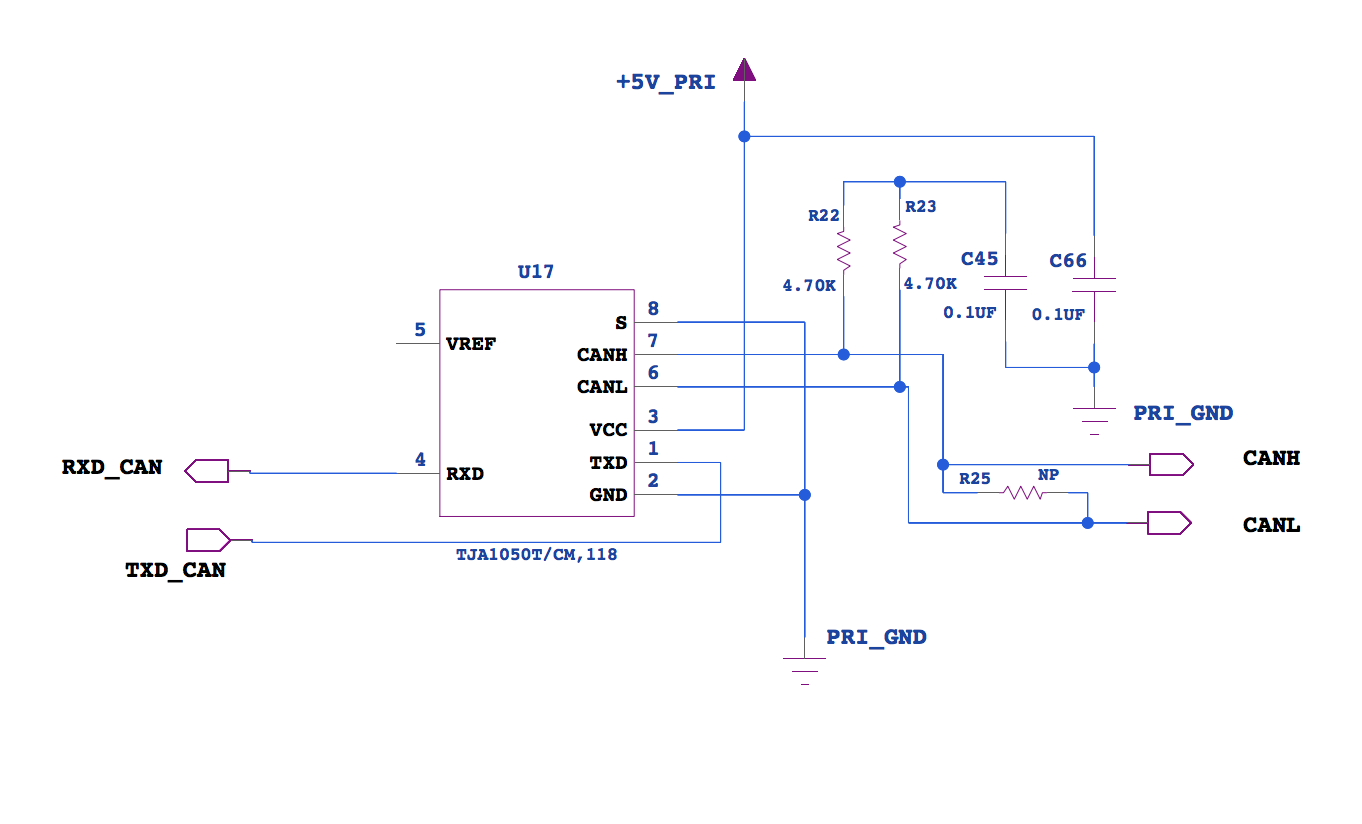
Our existing product has a TMS320f28031 with a TJA1050T CAN transceiver(shown in the first schematic snippet) which works perfectly fine. We have upgraded the same to a TMS320f28035 with a TJA1051T/3 CAN transceiver as shown in the second schematic snippet with the opto isolator. While testing this new design, I am having challenges to get the CAN up and running since the ECanaRegs.CANTRS.bit.TRS31 flag never goes to a low state stopping the transmission, and also no reception.

I tried the same code with the target configuration and memory map changed to abide to our old design, and that code gets the CAN functional. (I can transmit and receive to and from another controller) .
Note that although the 28035 has more pins, the GPIOs for CAN TX and RX are the same, thus ideally I see no need for a change in the initialization of the CAN module.

Am I missing out on something in the code because of the 28031-28035 change here?  Or does the new design portion on the schematic seem to be at fault here?

  • 28031 & 28035 are functionally identical from a CAN perspective. So, if your code runs fine on 28031 but not on a 28035, I’d suspect the 28035 hardware.


    TRS31 never gets cleared implies the transmission did not complete successfully. Did you scope the waveform on pin 1 of TJA1051?


    Did you try a lower bit-rate?


    It appears you are using split-termination. Is there a reason you are using 2 x 4.7K, instead of the standard 2 x 62?

  • Yes, I scoped pin 1, it seems to be stuck at a high voltage level.

    The lower bit rate isn't working either.

    I'll find out why the resistors are 2x4.7k. But I checked and its the same in our old working design where we have a different opto isolator chip.

    What is the implication of the transmission not being successful when the TRS31 is not cleared exactly? A failure from the eCAN module? or no acknowledgement after it tries to send the data?

    I checked the CANES register as well for checking the error status. No error flags have been raised.
  • Any data comes out of CANTX pin? If there is only one other node and it is not sending an ACK, the transmitter will keep of re-transmitting. Put your scope on single-acquisition and check if any data ever comes out of CANTX pin (at least once).


    The termination resistor value assumes significance with higher bit-rates.


    If TRS31 is not cleared, it means an ACK was not received from the other node. The problem could be anywhere in the in the connection between the 2 devices. You have to debug if stage-by-stage starting from the CANTX pin of the MCU.


    Please download my app.note SPRA876A and take a look at the debugging tips.

  • I didn't see any data coming out from the TX, just stuck high. And the code condition where TRS bit is cleared was never successful.

    Alright I'll do more debugging keeping these things in mind on Monday and I'll get back. Thank you for your input.

  • I isolated the processor chip from the circuitry that follows it and I did see signals on the processors CAN Tx pin. So looks like its something in that buffer - opto isolator - transceiver circuit which is causing a problem. Stage by stage debugging should solve it now.  

  • A pin connection for the transceiver had been overlooked. Fixing that solved it. Thank you for the guidance.