This thread has been locked.

If you have a related question, please click the "Ask a related question" button in the top right corner. The newly created question will be automatically linked to this question.

CCS/TMS320F28377S: DSP TO FPGA send data using DMA

Part Number: TMS320F28377S
Other Parts Discussed in Thread: C2000WARE

Tool/software: Code Composer Studio

  Hi

        Question: If I use EMIF, what is the upper limit of the transmission speed of DMA?

        In the datasheet:Throughput: four cycles/word (without arbitration). Does the 4 cycle here mean the cycle of the system? I did a test, the waveform is as follows:

       dsp_addr:EM1A

      dsp_ce1: EM1CS2

      dsp_dq:EM1D

      dsp_100m: EM1CLK,100M,The results obtained by the 200m clock.

      dsp_wr:EM1WE

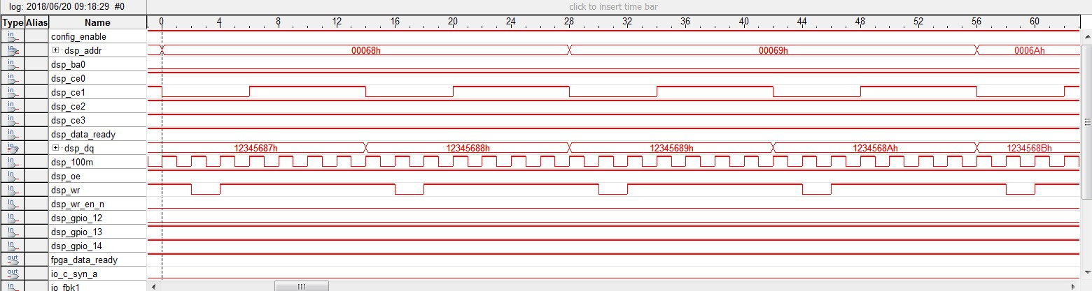
    You can see from the above figure,every 7 clocks(EM1CLK) will have a data.Can the speed here be improved?

    Part of the code is as follows:

    Procedure 1:

void EMIF1Setup(void)

{

            //Configure to run EMIF1 on full Rate (EMIF1CLK = CPU1SYSCLK)

            EALLOW;

            ClkCfgRegs.PERCLKDIVSEL.bit.EMIF1CLKDIV = 0x1;

            EDIS;


            EALLOW;


            //Disable Access Protection (CPU_FETCH/CPU_WR/DMA_WR)

            Emif1ConfigRegs.EMIF1ACCPROT0.all = 0x0;

            if (Emif1ConfigRegs.EMIF1ACCPROT0.all != 0x0)

            {

             ErrCount++;

            }


            // Commit the configuration related to protection. Till this bit remains set

            // content of EMIF1ACCPROT0 register can't be changed.

            Emif1ConfigRegs.EMIF1COMMIT.all = 0x1;

            if(Emif1ConfigRegs.EMIF1COMMIT.all != 0x1)

            {

            ErrCount++;

            }


            // Lock the configuration so that EMIF1COMMIT register can't be changed any more.

            Emif1ConfigRegs.EMIF1LOCK.all = 0x1;

            if (Emif1ConfigRegs.EMIF1LOCK.all != 1)

            {

             ErrCount++;

            }


            EDIS;


            //Configure GPIO pins for EMIF1

            setup_emif1_pinmux_async_32bit(0);

            Emif1Regs.ASYNC_CS2_CR.all =  (EMIF_ASYNC_ASIZE_32        | // 32Bit Memory Interface

                                                                                                EMIF_ASYNC_TA_1              | // Turn Around time of 2 Emif Clock

                                                                                                EMIF_ASYNC_RHOLD_1      | // Read Hold time of 1 Emif Clock

                                                                                                EMIF_ASYNC_RSTROBE_1 | // Read Strobe time of 4 Emif Clock

                                                                                                EMIF_ASYNC_RSETUP_1    | // Read Setup time of 1 Emif Clock

                                                                                                EMIF_ASYNC_WHOLD_1      | // Write Hold time of 1 Emif Clock

                                                                                                EMIF_ASYNC_WSTROBE_1             | // Write Strobe time of 1 Emif Clock

                                                                                                EMIF_ASYNC_WSETUP_1    | // Write Setup time of 1 Emif Clock

                                                                                                EMIF_ASYNC_EW_DISABLE             | // Extended Wait Disable.

                                                                                                EMIF_ASYNC_SS_DISABLE    // Strobe Select Mode Disable.

                                                                                                );

 }

Procedure 2:

void dma_init()

{

            volatile Uint16 transfer_cfg;

            DMAInitialize();

             DMACH5AddrConfig32bit(CFG_DATA_ADDR,&temp_buf_dma);

            DMACH5BurstConfig(BURST,2,1);

            transfer_cfg=sizeof(MCCfg);

            DMACH5TransferConfig(transfer_cfg,1,0);

            DMACH5ModeConfig(DMA_SPIATX,PERINT_ENABLE,ONESHOT_DISABLE,CONT_DISABLE

                        ,SYNC_DISABLE,SYNC_SRC,OVRFLOW_DISABLE,THIRTYTWO_BIT,CHINT_END,CHINT_ENABLE);

}

Thank you very much

  • xiaoq,

    This EMIF Application Report might be useful for you.

    It includes guidance for how to maximize EMIF throughput and includes measured benchmarks in an appendix.  There is also a DMA transfer example (emif_dc_dma) in C2000Ware.

    -Tommy

  • Tommy,

        In the EMIF Application Report, 'Figure 5. DMA: Asynchronous Writes',we can see from this diagram,throughput (MB/s) upper limit is near 115MB/S.

        My DSP typesis TMS320F28377DPTPS.Now the speed  of  DMA is 50MB/s.

         I have a question,All types of 28377 can be reached 115MB/S?

         When I was debugging,I found the 'Turn Around cycles' is too large,10 system clocks are taken.The code is as follows

         EMIF_DC_REGS[emifModule]->ASYNC_CS2_CR.bit.TA       = 0;

        How can I reduce it?

    Thank you for your precious time

  • Tommy,

    In the EMIF Application Report, 'Figure 5. DMA: Asynchronous Writes',we can see from this diagram,throughput (MB/s) upper limit is near 115MB/S.

    My DSP typesis TMS320F28377DPTPS.Now the speed of DMA is 50MB/s.

    I have a question,All types of 28377 can be reached 115MB/S?

    When I was debugging,I found the 'Turn Around cycles' is too large,10 system clocks are taken.The code is as follows

    EMIF_DC_REGS[emifModule]->ASYNC_CS2_CR.bit.TA = 0;

    How can I reduce it?

    Thank you for your precious time
  • xiaoq,

    Any F2837x device should be able to achieve the same benchmarks when using the same configuration settings. Are you using the same settings as what is listed in the benchmarks? It looked like your device was configured to use an EMIF clock of 100MHz, whereas the benchmarks are running with EMIF at 200MHz.

    Configuring TA to 0 is all that can be done to minimize the turnaround cycles. The turnaround cycles is only inserted when changing memory access modes (read and write). If you are mixing writes and reads then you would have performance closer to the Interleaved Writes and Reads plots.

    Finally, the transfer block size does make a difference in performance. Larger block transfers can take advantage of pipelining to minimize the effects of internal EMIF bus latency.

    -Tommy
  • Tommy,

        "It looked like your device was configured to use an EMIF clock of 100MHz",I modified the program,The code is as follows,EMIF at 200MHz.

    EALLOW;
    ClkCfgRegs.PERCLKDIVSEL.bit.EMIF1CLKDIV = 0x0;
    EDIS;

         Configuring TA to 0 is all that can be done to minimize the turnaround cycles.The code is as follows,Configuring TA to 0.

    Emif1Regs.ASYNC_CS2_CR.all = (EMIF_ASYNC_ASIZE_32 | // 32Bit Memory Interface

    EMIF_ASYNC_TA_1 | // 
    EMIF_ASYNC_RHOLD_1 | //
    EMIF_ASYNC_RSTROBE_4 | // 
    EMIF_ASYNC_RSETUP_1 | // 
    EMIF_ASYNC_WHOLD_1 | //
    EMIF_ASYNC_WSTROBE_1 | // 
    EMIF_ASYNC_WSETUP_1 | // 
    EMIF_ASYNC_EW_DISABLE | //
    EMIF_ASYNC_SS_DISABLE // 
    );

    As shown in the following figure,

    The CE signal takes up 7 clock cycles,High level takes up 4 clock cycles,this high level is TA.How can we further reduce the time of TA?

    Thank you very much.

  • xiaoq,

    What is your BURST size? You might try to set the DMA ONESHOT mode.

    If possible, you can also try the settings from \C2000Ware_XXXX\device_support\f2837xd\examples\cpu1\emif_dc_dma\cpu01\

    -Tommy