This thread has been locked.

If you have a related question, please click the "Ask a related question" button in the top right corner. The newly created question will be automatically linked to this question.

CCS/F28M36P63C2: Latch GPIO to high issue

Part Number: F28M36P63C2

Tool/software: Code Composer Studio

Hello,

Trying to turn on an LED for a fault condition in this project i am working on. Basically i am using GPIO 110, i have set it as output in GPDDIR register, set it to mux as a GPIO and i write a one into GPDSET register for the corresponding bit. But it does not latch the output data to high. When i monitor the bit in the watch window, it's value reads 0. What am i missing here?? should i be using the GPDDAT register instead?? because i tried that and it didn't turn on the LED either. Any help or suggestion is greatly appreciated.

Thank you,

Srini

  • Srini,

    First lets clarify the GPDxxx regiters use:

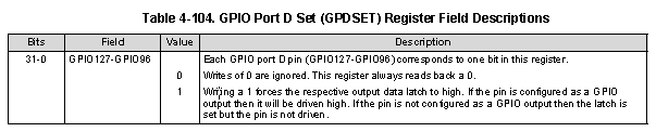
    The description of GPDSET is listed below, it will always read as a zero, this information can be found in the TRM.

    If you would like to see the current state of the pin please read the GPDDAT register.

    Second:

    • Have you handed GPIO access over to the C28 from the ARM core for GPIO 110?
    • Have you read back your configuration of GPIO110 using the memory browser?
      • Its possible you are having a EALLOW issue or something else is stepping on your configuration.

    Regards,
    Cody 

  •  // LED's configured as outputs
        EALLOW;
        GpioG1CtrlRegs.GPDMUX1.bit.GPIO107= 0;//Set mux to GPIO (default)  //GreenLED
        GpioG1CtrlRegs.GPDDIR.bit.GPIO107 = 1; //Set as output
    
        GpioG1CtrlRegs.GPDMUX1.bit.GPIO110= 0;//Set mux to GPIO (default)  //AmberLED
        GpioG1CtrlRegs.GPDDIR.bit.GPIO110 = 1;//Set as output
    
        GpioG1CtrlRegs.GPDMUX1.bit.GPIO111= 0;//Set mux to GPIO (default)  //RedLED
        GpioG1CtrlRegs.GPDDIR.bit.GPIO111 = 1;//Set as output
    
        GpioG1DataRegs.GPDSET.bit.GPIO107=1;
        GpioG1DataRegs.GPDSET.bit.GPIO110=1;
        GpioG1DataRegs.GPDSET.bit.GPIO111=1;
        EDIS;

    Thank you, Cody. I checked the GPDDAT.bit.GPIO110 and it is set to 1. I have given access to all the GPIO'S for the C28 Core. When i observe the output from that pin on the oscilloscope, it doesn't go high and remains low.  Before i write to these registers i enabled EALLOW and disable it after writing to them.

    I verified the contents of GPDDAT register and it is accurate with regards to what i want inside it. Any idea why that's happening?

    Srini

  • Srini,

    Srinivasan Venkatasubramani said:
    I verified the contents of GPDDAT register and it is accurate with regards to what i want inside it.

    So you can see 1 and 0 changing in the GPDDAT register for GPIO110?

    What do you have connected to GPIO110's pin? Are there any pull-down resistors? is it possible that it was accidentally shunted to ground?

    Regards,
    Cody 

  • At this point i don't expect it to change 1 and 0 because i wanted it pulled high constantly. Not trying to blink the LED. Just trying to turn it on. And
    my LED anode is connected to the GPIO and the cathode is grounded via a 2.2kohm pull down resistor.
  • Srini,

    I recognize that you don't wish to toggle the GPIO, but this will prove if you can force it to the high and low state.\

    Regards,
    Cody 

  • Thank you, cody. I resolved this.
  • Great,
    Please post a summary of what you needed to change to get this working. It will help others in the future!!

    Regards,
    Cody
  • Well, what i was doing wrong was my board had a few GPIO's designated to behave like inputs at all times. I had overlooked this and tried to set them as outputs and that's why i had issues.

    In any case i think a general thumb rule is, just to make sure there are no hardware limitations on your GPIO's. And sometimes you could have internal pullup's due to your board design or otherwise, which means you need to disable them by monitoring the GPIOPUD register in M3 master system.

    All GPIO's are default mux'd as a GPIO, but it doesn't hurt to be safe. Set them as outputs using GPxDIR register and then you can set or clear the latch to control your GPIO high or low using GPxSET and GPxCLR. To monitor if they have been pulled high or low, look at the contents of GPxDAT.

    Hope it helps,
    Srini