This thread has been locked.

If you have a related question, please click the "Ask a related question" button in the top right corner. The newly created question will be automatically linked to this question.

TMS320F28379D: TMS320F28379D EPWM programable delay on both external rising edge and falling edge signal

Part Number: TMS320F28379D

Hi all,

I'm developiong a power converter using TMS320F28379D. And here is a special signal timing.

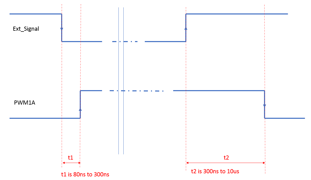
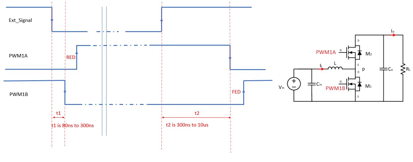
A external signal from my sensing circuit will connect to the GPIOs and configure as SYNC_in, as shown Ext _signal. A programable t1 and t2 is followed by the falling edge and rising edge. 

I know I could do it with 2 EWPM channels, by connecting the Ext_signal to two SYNC_in (EPWN1_SYNC_in and EPWM2_SYNC_in). The EPWM2 can generate t1 delay on the EPWM2A  output pin (the timing of EWPM2_SYNC_in and EPWM2_CMPA) and connect the EPWM2A pin to EPWM1 T1 to do an action set. 

t2 delay can be directly done by EPWN1_SYNC_in and EPWM1_CMPA.

Two Questions here. 1) Is there other way that I can do it only using 1 EWPM channel?

2) EPWM_SYNC_in to EPWM1A has a minimal delay of 80ns accroding to my test on the scope. Is there a way to make it faster?

  • Hi,

    There are multiple ways of achieving this - it could be a bit tricky as it's not conventional usage.

    1. Regarding using single EPWM module -
    Did you explore the option of using dead band module for this?
    Please refer to "Figure 14-33. Configuration Options for the Dead-Band Submodule" - in particular S8 configuration.
    DBCTL[DEDBMODE] allows you to apply both rising and falling edge delays (different values) on the same signal.
    first generate the waveform replicating the Sync input and apply different delays using above.
    To replicate the PWM waveform with external signal - again you can do in different ways.
    One option is to use the same external input GPIO as Trip (generate DC event and use it as T1/T2 in action qualifier using T1/T2SEL regs). You can use it as Sync as well to generate one edge and T1/T2 to generate other PWM edge with no delay, and then apply delay using Deadband.

    2. There will be some inherent delay form Sync to PWMA output. If you have synchronizers inside GPIO enabled on Sync input, that will be adding additional delay. You can disable that and try.
  • Hi Thank you for your solution.Your answer solved the problem I described. But can you help me to look deeper where I already used Active High Complementary. It is a application of a Synchronous Boost PFC above 500 kHz. I already configure RED and FED. It is the 1A and 1B falling edge (t1 and t2) to do the switching instant and determines the actual converter duty. So I may not have the freedom to use RED and FED. 

    I'm trying to see if the DCEVTFILT and DCFCTL could handle the application. Do you have any suggestions?