Part Number: TMS320F28335
I am using the following code to take a three-phase waveform as input from the ADC. The sampling frequency is set by using TIMER0 and the sampling frequency is set to 10,000Hz. The EPWM interrupt is redundant for now and is for future use.
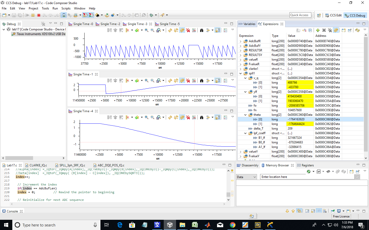
My input waveform is between 0 and 3V and is shifted down by 1.5V inside the DSP. I am using a predefined code for PLL i.e "SPLL_3ph_SRF_IQ" for the synchronization of my three-phase input waveforms. However, the frequency "f_n" and "f_o" (Set Frequency and Oscillator Frequency) are not matching after running the code and are continuously changing as I am watching in the WATCH VARIABLE list. The PLL constants I have used is the one given in the excel sheet ( "spll_coeff_compute") which is defined for 10,000Hz. I am using IQ math for calculation of ADC input values.
| Fs | 10000 | |
| Ts | 0.0001 | |
| B0 | 223.4194 | |
| B1 | -220.901 |
Please let me know if I am doing any mistake here.
#include "DSP2833x_Device.h"
#include "IQmathLib.h"
#include "Solar_IQ.h"
#define AdcBufLen 200
#define AdcFsVoltage _IQ(3.0) // ADC full scale voltage
#define sub _IQ(1.5) // ADC full scale voltage
// external function prototypes
float RESULTSR[200];
float RESULTSY[200];
float RESULTSB[200];
float FvalueR[200];
float FvalueY[200];
float FvalueB[200];
//float alpha[100];
//float beta[100];
float A[200];
float B[200];
float C[200];
_iq AdcBufR[AdcBufLen]; // ADC results buffer
_iq AdcBufY[AdcBufLen]; // ADC results buffer
_iq AdcBufB[AdcBufLen];
_iq valueR[AdcBufLen];
_iq valueY[AdcBufLen];
_iq valueB[AdcBufLen];
extern void InitSysCtrl(void);
extern void InitPieCtrl(void);
extern void InitPieVectTable(void);
extern void InitCpuTimers(void);
extern void ConfigCpuTimer(struct CPUTIMER_VARS *, float, float);
CLARKE_IQ clarke1;
SPLL_3ph_SRF_IQ spll1;
ABC_DQ0_POS_IQ abc_dq0_pos1;
ABC_DQ0_POS_IQ abc_dq0_pos2;
ABC_DQ0_POS_IQ abc_dq0_pos3;
// Prototype statements for functions found within this file.
void Gpio_select(void);
void Setup_ePWM1A(void);
interrupt void cpu_timer0_isr(void);
interrupt void adc_isr(void);
//###########################################################################
// main code
//###########################################################################
void main(void)
{
int counter=0; // binary counter for digital output
InitSysCtrl(); // Basic Core Init from DSP2833x_SysCtrl.c
EALLOW;
SysCtrlRegs.WDCR= 0x00AF; // Re-enable the watchdog
EDIS; // 0x00AF to NOT disable the Watchdog, Prescaler = 64
DINT; // Disable all interrupts
Gpio_select(); // GPIO9, GPIO11, GPIO34 and GPIO49 as output
// to 4 LEDs at Peripheral Explorer
Setup_ePWM1A(); // init of ePWM1A
InitAdc(); // Basic ADC setup, incl. calibration
AdcRegs.ADCTRL1.bit.SEQ_CASC = 1; // Cascaded Sequencer Mode
AdcRegs.ADCTRL1.bit.CONT_RUN = 0; // No Continuous run
AdcRegs.ADCTRL1.bit.CPS = 0; // prescaler = 1
AdcRegs.ADCTRL2.bit.EPWM_SOCA_SEQ1 = 0; // Disable EPWM_SOCA to start SEQ1
AdcRegs.ADCTRL2.bit.INT_ENA_SEQ1 = 1; // Enable SEQ1 interrupt
AdcRegs.ADCTRL2.bit.INT_MOD_SEQ1 = 0; // with every EOS
AdcRegs.ADCTRL3.bit.ADCCLKPS = 3; // Divide HSPCLK by 6
AdcRegs.ADCMAXCONV.all = 2; // 1 Conversion per start
AdcRegs.ADCCHSELSEQ1.bit.CONV00 = 0; // Setup ADCINA2 as input channel.
AdcRegs.ADCCHSELSEQ1.bit.CONV01 = 1;
AdcRegs.ADCCHSELSEQ1.bit.CONV02 = 2;
InitPieCtrl(); // basic setup of PIE table; from DSP2833x_PieCtrl.c
InitPieVectTable(); // default ISR's in PIE
EALLOW;
PieVectTable.TINT0 = &cpu_timer0_isr;
PieVectTable.ADCINT = &adc_isr;
EDIS;
InitCpuTimers(); // basic setup CPU Timer0, 1 and 2
ConfigCpuTimer(&CpuTimer0,150,100);
spll1.fn=(int32)(_IQtoIQ21(_IQ(50)));
spll1.delta_T=(int32)(_IQtoIQ21(_IQ(0.0001)));
PieCtrlRegs.PIEIER1.bit.INTx7 = 1;
PieCtrlRegs.PIEIER1.bit.INTx6 = 1; // ADC
IER |=1;
EINT;
ERTM;
CpuTimer0Regs.TCR.bit.TSS = 0; // start timer0
while(1)
{
while(CpuTimer0.InterruptCount == 0);
CpuTimer0.InterruptCount = 0;
EALLOW;
SysCtrlRegs.WDKEY = 0x55; // service WD #1
EDIS;
counter++;
}
}
void Gpio_select(void)
{
EALLOW;
GpioCtrlRegs.GPAMUX1.all = 0; // GPIO15 ... GPIO0 = General Puropse I/O
GpioCtrlRegs.GPAMUX1.bit.GPIO0 = 1; // ePWM1A active
GpioCtrlRegs.GPAMUX2.all = 0; // GPIO31 ... GPIO16 = General Purpose I/O
GpioCtrlRegs.GPBMUX1.all = 0; // GPIO47 ... GPIO32 = General Purpose I/O
GpioCtrlRegs.GPBMUX2.all = 0; // GPIO63 ... GPIO48 = General Purpose I/O
GpioCtrlRegs.GPCMUX1.all = 0; // GPIO79 ... GPIO64 = General Purpose I/O
GpioCtrlRegs.GPCMUX2.all = 0; // GPIO87 ... GPIO80 = General Purpose I/O
GpioCtrlRegs.GPADIR.all = 0;
GpioCtrlRegs.GPBDIR.all = 0; // GPIO63-32 as inputs
GpioCtrlRegs.GPCDIR.all = 0; // GPIO87-64 as inputs
EDIS;
}
void Setup_ePWM1A(void)
{
EPwm1Regs.TBCTL.bit.CLKDIV = 0; // CLKDIV = 1
EPwm1Regs.TBCTL.bit.HSPCLKDIV = 0; // HSPCLKDIV = 1
EPwm1Regs.TBCTL.bit.CTRMODE = 2; // up - down mode
EPwm1Regs.AQCTLA.all = 0x0060; // set ePWM1A on CMPA up
// clear ePWM1A on CMPA down
EPwm1Regs.TBPRD = 37500; // 2KHz - PWM signal
// TBPRD = fCPU / ( 2 * fPWM *CLKDIV * HSPCLKDIV)
// TBPRD = 150MHz / (2 * 2kHz * 1 *1)
// TBPRD = 37500
EPwm1Regs.CMPA.half.CMPA = 18750; // 50% duty cycle
// CMPA = (100% - duty cycle)*TBPRD
// CMPA = 0.75 * 37500 = 28125
}
interrupt void cpu_timer0_isr(void)
{
CpuTimer0.InterruptCount++;
AdcRegs.ADCTRL2.bit.SOC_SEQ1 = 1; // start ADC by software
EALLOW;
SysCtrlRegs.WDKEY = 0xAA; // service WD #2
EDIS;
PieCtrlRegs.PIEACK.all = PIEACK_GROUP1;
PieCtrlRegs.PIEACK.all = PIEACK_GROUP1;
}
interrupt void adc_isr(void)
{
static Uint16 index=0; // index into ADC buffers
AdcBufR[index] = _IQmpy(AdcFsVoltage, _IQ16toIQ( (_iq)AdcRegs.ADCRESULT0) );
AdcBufY[index] = _IQmpy(AdcFsVoltage, _IQ16toIQ( (_iq)AdcRegs.ADCRESULT1) );
AdcBufB[index] = _IQmpy(AdcFsVoltage, _IQ16toIQ( (_iq)AdcRegs.ADCRESULT2) );
A[index] = AdcBufR[index];
B[index] = AdcBufY[index];
C[index] = AdcBufB[index];
valueR[index] = _IQmpy(AdcFsVoltage, _IQ16toIQ( (_iq)AdcRegs.ADCRESULT0) )-(sub);
FvalueR[index] = _IQtoF(valueR[index]);
valueY[index] = _IQmpy(AdcFsVoltage, _IQ16toIQ( (_iq)AdcRegs.ADCRESULT1) )-(sub);
FvalueY[index] = _IQtoF(valueY[index]);
valueB[index] = _IQmpy(AdcFsVoltage, _IQ16toIQ( (_iq)AdcRegs.ADCRESULT2) )-(sub);
FvalueB[index] = _IQtoF(valueB[index]);
RESULTSR[index] = _IQtoF( AdcBufR[index] );
RESULTSY[index] = _IQtoF( AdcBufY[index] );
RESULTSB[index] = _IQtoF( AdcBufB[index] );
clarke1.a= valueR[index];
clarke1.b= valueY[index];
clarke1.c= valueB[index];
CLARKE_IQ_MACRO(clarke1);
abc_dq0_pos1.a = _IQmpy(AdcBufR[index],_IQ(0.5));
abc_dq0_pos1.b = _IQmpy(AdcBufY[index],_IQ(0.5));
abc_dq0_pos1.c = _IQmpy(AdcBufB[index],_IQ(0.5));
abc_dq0_pos1.sin=_IQsin((spll1.theta[1])<<3); // Q24 to Q21
abc_dq0_pos1.cos=_IQcos((spll1.theta[1])<<3); // Q24 to Q21
ABC_DQ0_POS_IQ_MACRO(abc_dq0_pos1); // Q24 to Q21
spll1.v_q[0] = (int32)(_IQtoIQ21(abc_dq0_pos1.q));
SPLL_3ph_SRF_IQ_FUNC(&spll1);
index++;
// Increment the index
if(index == AdcBufLen)
index = 0; // Rewind the pointer to beginning
// Reinitialize for next ADC sequence
AdcRegs.ADCTRL2.bit.RST_SEQ1 = 1; // Reset SEQ1
AdcRegs.ADCST.bit.INT_SEQ1_CLR = 1; // Clear INT SEQ1 bit
PieCtrlRegs.PIEACK.all = 1; // Acknowledge interrupt to PIE
}
//===========================================================================
// End of SourceCode.
//===========================================================================