This thread has been locked.

If you have a related question, please click the "Ask a related question" button in the top right corner. The newly created question will be automatically linked to this question.

CCS/TMS320F28027: Interfacing of TMS320F28027 with Vinculum with 13 clock sequence

Part Number: TMS320F28027

Tool/software: Code Composer Studio

Hello,

The SPI interface with vinculum is differs from most other implementations in that it uses a 13 clock sequence to transfer a single byte of data. The first step is to send 0x1800 to establish a communication.

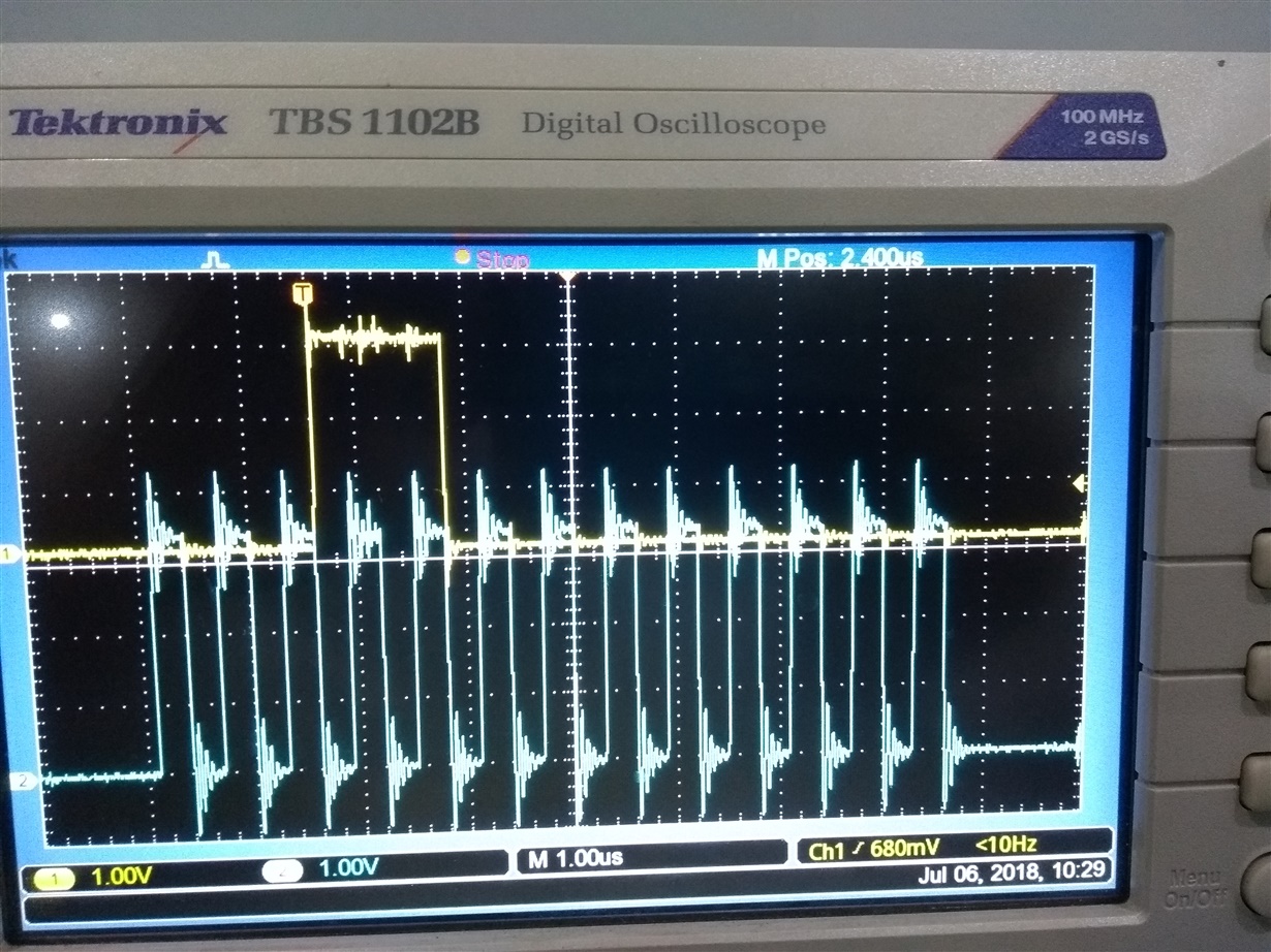
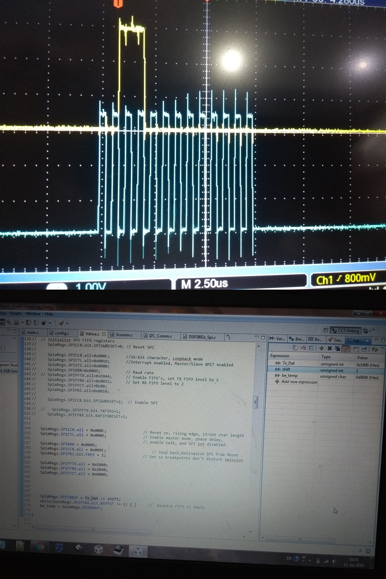
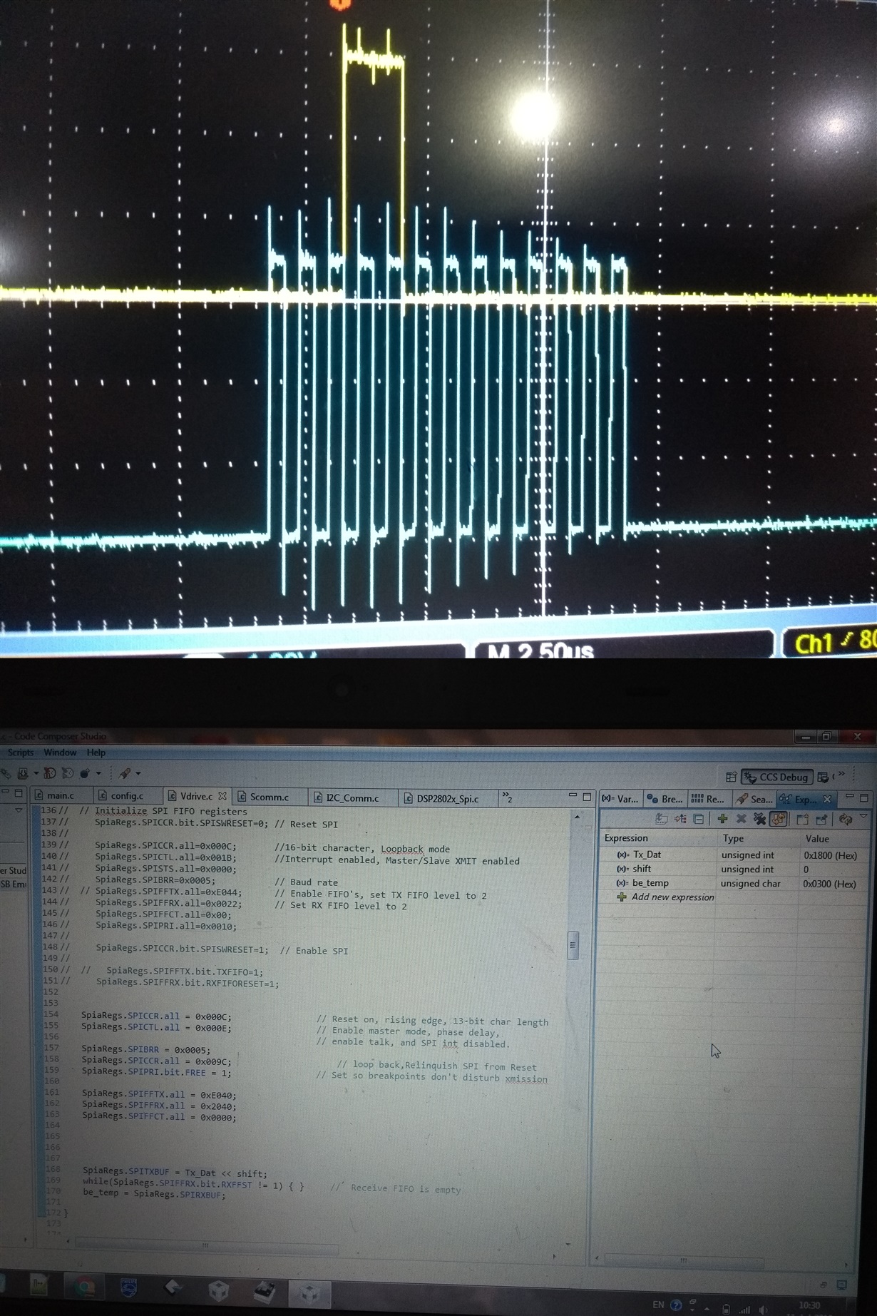
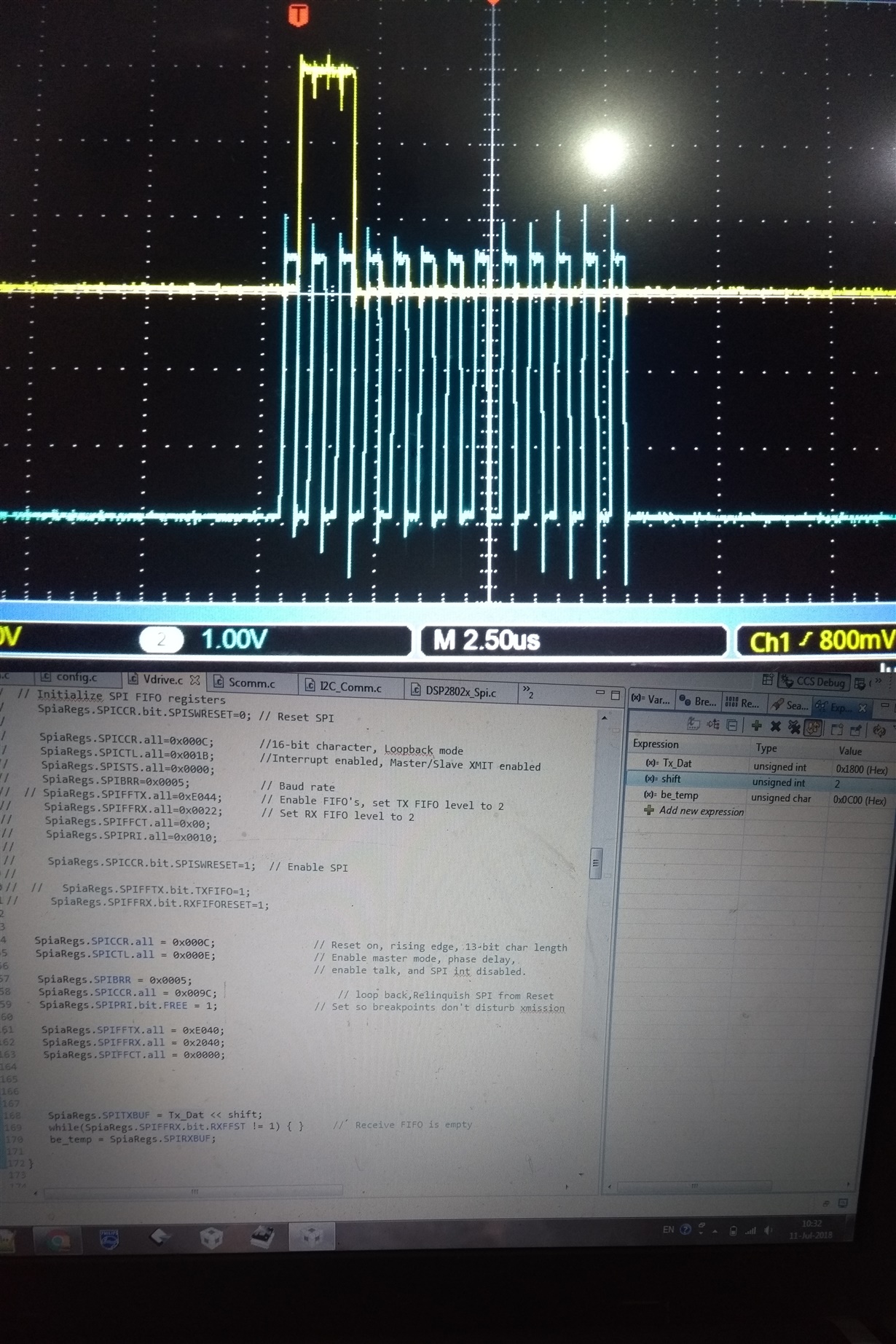
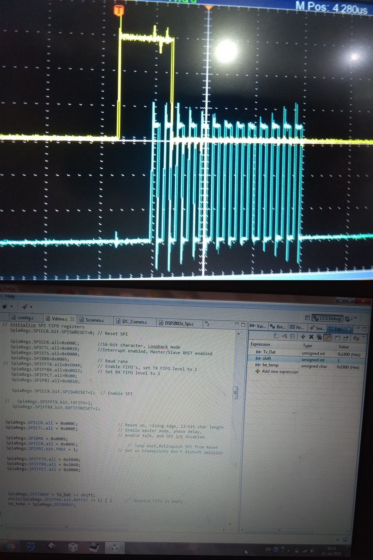
When i send this data from LPC2148 processor then communication establish. But when send from TMS320F28027 communication isn't establish. Because data is not transmitting in such way as transmit by LPC2148, i attached pics to clear my issue. First, 2 pics show Transmission of 0x1800 from LPC 2148 to vinculum (13 clock sequence) and the third one show the transmission of 0x1800 from TMS320F28027 to vinculm (13 clock sequence)

  issue.

void SSPIInit_Vdrive(void)
{
   SpiaRegs.SPICCR.all = 0x000C;        // Reset on,CLK Polarity : data is output on rising edge, 13-bit char length

   SpiaRegs.SPICTL.all = 0x000E;         // Data is output one half-cycle before the first rising edge of the SPICLK, master mode, enable talk, and SPI int disabled.

   SpiaRegs.SPIBRR = 0x0005;

   SpiaRegs.SPICCR.all = 0x008C;        // Relinquish SPI from Reset
   SpiaRegs.SPIPRI.bit.FREE = 1;         // Set so breakpoints don't disturb xmission

   SpiaRegs.SPIFFTX.all = 0xE040;
   SpiaRegs.SPIFFRX.all = 0x2040;
   SpiaRegs.SPIFFCT.all = 0x0;
}

void SPI_Tx (void)

{

     SpiaRegs.SPITXBUF = 0x1800 << 3;

}

  • Hi Sharique,

    Why are you left-adjusting 0x1800 by three?

    Your char value is set to 13 so only the 13 most significant bits will get sent, but 0x1800 is already a 16 bit value so I do not think you need to shift anything.

    Thank you,

    Marlyn

  •  Hi Marlyn,

                       Thanks for your response. When i send data i.e., 0x1800 as 13 bit char length without shifting then i got 0x0300 in received variable, and when sending by left shifting by three then i got 0x1800, checked via loopback mode and attached pic is the signal that what is going on bus without shifting.

    And i don't understand that the MOSI line of LPC2148 in above question is active high then send data and return back to it's high state and when send it  by TMS320F28027 MOSI line is active low then send data and back to it's low state and what's that extra bit added in the beginning of that data.

  • Hi Sharique,
    I see, you are trying to send 0x1800, but without the leading zeros on the most significant bit side. Makes sense if that is what you need to send.

    Do you have a pullup on the MOSI line of the LPC2148? If so that could be the reason that it is active high, or maybe you have enabled a pull down on the F28027?

    The extra bit when sending data through the LPC2148 could be from the way the SPI works for that device. It might be returning to its previous state before being driven active high.

    Best Regards,
    Marlyn
  • hello ma'm,
    Thanks for your reply.
    .............. No there is no external pull up on MOSI Line of LPC2148 and i already enabled an internal pull up on MOSI Line of TMS320F28027.
    .............. The extra bit is not on LPC2148 data line, it's on TMS320F28027 as i mentioned above the two images with active high MOSI are of LPC2148 and third one with active low MOSI is of TMS320F28027. when i send 0x1800 << 3 then what is the extra bit on that line of TMS320F28027.

    ........... now i'm going to describe my issue, I have code of LPC2148 interfacing with vinculum FTDI chip. SPI interface with vinculum is differs from most other implementations in that it uses a 13 clock sequence to transfer a single byte of data.
    Interfacing of microcontroller with USB Pen Drive via vinculum FTDI is ok. We have exe file of vinculum's software. I notice that a single byte is transmitted by LPC2148 with 13 bit character length or 13 clock sequence without any shifting and without any concept of MSB first and then LSB as shown in third image Tx = 0x1800 because according to LPC2148's refrence manual it's register adjust that byte automatically whether it has any character length. Means, vinculum receives data in a single transfer without concept of MSB LSB.
    ............ Now i'm going to replace LPC2148 by TMS320F28027, as i have only exe file of vinculum in which i can't make change in vinculum's software. So, how i can transmit a byte in a single transfer from TMS320F28027 with 13 bit character length to Vinculum FTDI chip.
    I checked it in loopback mode when transmit a byte 0x1800 in a single transfer without shifting or without MSB first and then LSB .
    The Received value is 0x0300. It's the main issue that vinculum can't recognize it as 0x1800 and communication not occur.

    Thanks & Regards,
    Sharique
  • Sharique,

    If you want to transmit 0x1800 in a single transfer without shifting the content in the transmit register, then you will need to shift the contents of the received register by three in order to avoid getting 0x0300. This will allow you to get 0x1800 in the received variable when you check using loopback.

    Now, if you do shift 0x1800 by three when assigning it to the transmit register you get 0x1800 in the received register without needing to shift that one. Is the connection still not made in that case? My apologies if this sounds redundant just trying to understand what is happening.

    Regards,

    Marlyn

  • Hello ma'm,

    You : If you want to transmit 0x1800 in a single transfer without shifting the content in the transmit register, then you will need to shift the contents of the received register by three in order to avoid getting 0x0300.

    me : Actually the receiving device is vinculum FTDI chip and i have only exe file of that. So, i can't make any change in receiving device software.

    And that device receive data as a single byte without shifting and and without MSB LSB concept as the data transmitted by LPC 2148.

    You :  if you do shift 0x1800 by three when assigning it to the transmit register you get 0x1800 in the received register .

    Me : I already did this but no communication occurs between TMS320F28027 and Vinculum FTDI Chip as the transmitting data signal is different from the actual one . I attached pics to this conversation to understand my issue by shifting from 0 to 3 what is the extra bit on the biginning of data li ne when shift by three.

  • Sharique,
    The extra bit could be from when the CS goes to active low.

    Do you know what kind of clock polarity and phase you had when using the LPC2148 processor?

    Also, how are you verifying if communication is getting established or not?


    Best Regards,
    Marlyn

  • Hello Mam,
    Ya i already know clock polarity and phase used in LPC2148. Same i used for TMS320F28027.
    Well, May be i'm on wrong way as the conclusion is that LPC2148 has the property to send any byte in a single transfer via SPI whether byte has any bit character length. But in TMS320F28027 if we choose 13 bit character length then data should be sent MSB first and then LSB or by shifting . So, we have to make change in vinculum's software for that we have to communicate with vinculum tech support becoz vinculum is the receiver.

    Thanks & Regards,
    Sharique
  • Sharique,
    Have you tried communicating with the vinculum tech support yet?


    Best Regards,
    Marlyn
  • Hi Sharique,
    Is there any update on the status of your problem?

    Best,
    Marlyn
  • Hello Ma'am,
    Ya i'm in contact with the HOD of other department (department working on LPC2148), coz i'm new in this R&D unit so from that department it's possible to whom i will contact regarding to vinculum's software as they know the links. After all of this i'll back to you to acknowledge about my issue's solution.

    Thanks & Regards,
    Sharique
  • Okay, thank you. Looking forward to your reply.


    Best Regards,
    Marlyn
  • Hello ma'am,
    Ya i got the solution, there is a little bit change in the code of DSP TMS320F28027 according to vinculum FTDI chip. Now, it's fine interfacing of TMS320F28027 with USB Pen Drive via vinculum. Thanks a lot ma'am for your cooperation and guidance.

    Ma'am, Now i'm indulge in an another issue i.e. interfacing with RTC via I2C. I used I2C bus for EEPROM M24256 and RTC MSP7940N . It's working fine with EEPROM M24256 via I2C but not with RTC.

    Issue is the Transmission of slave address. Slave address of EEPROM M24256 is 0x50 so it easily transmitted in 7-Bit addressing mode . But slave address of MCP7940N is 0xDE. For this address 10-Bit addressing mode is compatible. But RTC IC can't accept it in 10-Bit addressing mode.So, how could i transmit it in 7-Bit addressing mode.


    Thanks & Regards,
    Sharique
  • Hi Sharique,

    I am so glad that it was able to work for you!
    Could you please create a new thread with the problem you are now seeing? That way you will be able to get the help you need more directly.


    Best Regards,
    Marlyn

  • Hello ma'am,

    RTC issues solved by transmitting slave address shifting by one i.e., 0xDE >> 1.

    Thanks & Regards,

    Sharique