Part Number: TMS320F28069
Hi everyone!
I'm a newbie to DSP-programming who has been dealing with a problem for a couple of time. So I hope some of you can help me.
My goal is to use the built-in ADC for converting various signals (only one at the same time) - for testing purposes I chose a sine, which comes from a waveform generator. I already checked the signal, after passing the amplifier and such stuff, via oscilloscope and the sine reaches the corresponding pin unbiased, so I think I can exclude problems in the circuit.
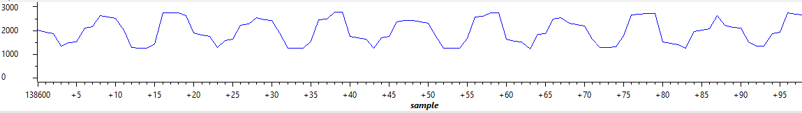
Due to I'm quite new to this matter, I followed one of TI's code examples (see code below). The positive thing is, that the AD-conversion "works", so I managed to get the ADC started. The issue is, that the conversion doesn't look very similar to a sine (see picture).
I tried to use the ePWM (as suggested in the example) and the CPU timer as trigger, but both basically lead to the same result. In the further text I'm referring to the version with the CPU timer, because it seems kind of more "intuitive" to me. The input signal is a 60kHz sine, so a 2µs timer for the sampling-rate should be enough. I guessed that using a single SOC might cause performance problems (which maybe would lead to the unpretty result), so I tried to use 4 of them (as mentioned in the handbook), but there was no improvement.
I have no idea, why the output looks that wrong, maybe some of you can help me?
Thank you!
PS: The code:
#include "DSP28x_Project.h" // Device Headerfile and Examples Include File
// Prototype statements for functions found within this file.
__interrupt void adc_isr(void);
void Adc_Config(void);
// Global variables used in this example:
Uint16 LoopCount;
Uint16 ConversionCount;
#define Anz 100
Uint16 Voltage2[Anz];
main()
{
// Step 1. Initialize System Control:
// PLL, WatchDog, enable Peripheral Clocks
// This example function is found in the F2806x_SysCtrl.c file.
InitSysCtrl();
// Step 2. Initialize GPIO:
// This example function is found in the F2806x_Gpio.c file and
// illustrates how to set the GPIO to it's default state.
// InitGpio(); // Skipped for this example
// Step 3. Clear all interrupts and initialize PIE vector table:
// Disable CPU interrupts
DINT;
// Initialize the PIE control registers to their default state.
// The default state is all PIE interrupts disabled and flags are cleared.
// This function is found in the F2806x_PieCtrl.c file.
InitPieCtrl();
// Disable CPU interrupts and clear all CPU interrupt flags:
IER = 0x0000;
IFR = 0x0000;
// Initialize the PIE vector table with pointers to the shell Interrupt
// Service Routines (ISR).
// This will populate the entire table, even if the interrupt is not used in this example. This is useful for debug purposes.
// The shell ISR routines are found in F2806x_DefaultIsr.c.
// This function is found in F2806x_PieVect.c.
InitPieVectTable();
// Interrupts that are used in this example are re-mapped to
// ISR functions found within this file.
EALLOW; // This is needed to write to EALLOW protected register
PieVectTable.ADCINT1 = &adc_isr;
EDIS; // This is needed to disable write to EALLOW protected registers
//memcpy( &RamfuncsRunStart, &RamfuncsLoadStart, &RamfuncsLoadEnd - &RamfuncsLoadStart);
// Step 4. Initialize all the Device Peripherals:
// This function is found in F2806x_InitPeripherals.c
// InitPeripherals(); // Not required for this example
InitAdc(); // For this example, init the ADC
// Step 5. User specific code, enable interrupts:
// Enable ADCINT1 in PIE
PieCtrlRegs.PIEIER1.bit.INTx1 = 1; // Enable INT 1.1 in the PIE
IER |= M_INT1; // Enable CPU Interrupt 1
EINT; // Enable Global interrupt INTM
ERTM; // Enable Global realtime interrupt DBGM
LoopCount = 0;
ConversionCount = 0;
// Configure ADC
EALLOW;
AdcRegs.ADCSAMPLEMODE.all = 0;
AdcRegs.ADCCTL2.bit.ADCNONOVERLAP = 1; // Enable non-overlap mode
AdcRegs.ADCCTL1.bit.INTPULSEPOS = 1; // ADCINT1 trips after AdcResults latch
AdcRegs.INTSEL1N2.bit.INT1E = 1; // Enabled ADCINT1
AdcRegs.INTSEL1N2.bit.INT1CONT = 0; // Enable ADCINT1 Continuous mode
AdcRegs.INTSEL1N2.bit.INT1SEL = 3; // setup EOC1 to trigger ADCINT1 to fire
AdcRegs.ADCSOC0CTL.bit.CHSEL = 1; // set SOC0 channel select to ADCINA1
AdcRegs.ADCSOC1CTL.bit.CHSEL = 1; // set SOC1 channel select to ADCINA1
AdcRegs.ADCSOC2CTL.bit.CHSEL = 1; // set SOC0 channel select to ADCINA0
AdcRegs.ADCSOC3CTL.bit.CHSEL = 1; // set SOC1 channel select to ADCINA1
AdcRegs.ADCSOC0CTL.bit.TRIGSEL = 1; // set SOC0 start trigger on EPWM1A, due to round-robin SOC0 converts first then SOC1
AdcRegs.ADCSOC1CTL.bit.TRIGSEL = 1; // set SOC1 start trigger on EPWM1A, due to round-robin SOC0 converts first then SOC1
AdcRegs.ADCSOC2CTL.bit.TRIGSEL = 1; // set SOC2 start trigger on EPWM1A, due to round-robin SOC0 converts first then SOC1
AdcRegs.ADCSOC3CTL.bit.TRIGSEL = 1; // set SOC3 start trigger on EPWM1A, due to round-robin SOC0 converts first then SOC1
AdcRegs.ADCSOC0CTL.bit.ACQPS = 6; // set SOC0 S/H Window to 7 ADC Clock Cycles, (6 ACQPS plus 1)
AdcRegs.ADCSOC1CTL.bit.ACQPS = 6; // set SOC1 S/H Window to 7 ADC Clock Cycles, (6 ACQPS plus 1)
AdcRegs.ADCSOC2CTL.bit.ACQPS = 6; // set SOC0 S/H Window to 7 ADC Clock Cycles, (6 ACQPS plus 1)
AdcRegs.ADCSOC3CTL.bit.ACQPS = 6; // set SOC1 S/H Window to 7 ADC Clock Cycles, (6 ACQPS plus 1)
//AdcRegs.SOCPRICTL.bit.ONESHOT = 1;
AdcRegs.SOCPRICTL.bit.SOCPRIORITY = 0;
EDIS;
//ePWM trigger - not used
/*
// Assumes ePWM1 clock is already enabled in InitSysCtrl();
EPwm1Regs.ETSEL.bit.SOCAEN = 1; // Enable SOC on A group
EPwm1Regs.ETSEL.bit.SOCASEL = 4; // Select SOC from CMPA on upcount
EPwm1Regs.ETPS.bit.SOCAPRD = 1; // Generate pulse on 1st event
EPwm1Regs.CMPA.half.CMPA = 0x0010; // Set compare A value 0x0080
EPwm1Regs.TBPRD = 0x1f; // Set period for ePWM1
EPwm1Regs.TBCTL.bit.CTRMODE = 0; // count up and start
*/
InitCpuTimers(); // For this example, only initialize the Cpu Timers
// Configure CPU-Timer 0, 1, and 2 to interrupt every second:
// 80MHz CPU Freq, 1 second Period (in uSeconds)
ConfigCpuTimer(&CpuTimer0, 90, 2);
CpuTimer0Regs.TCR.all = 0x4000; // Use write-only instruction to set TSS bit = 0
// Wait for ADC interrupt
for(;;)
{
LoopCount++;
}
}
__interrupt void adc_isr(void)
{
Voltage2[ConversionCount] = AdcResult.ADCRESULT0;
ConversionCount++;
Voltage2[ConversionCount] = AdcResult.ADCRESULT1;
ConversionCount++;
Voltage2[ConversionCount] = AdcResult.ADCRESULT2;
ConversionCount++;
Voltage2[ConversionCount] = AdcResult.ADCRESULT3;
// If Anz conversions have been logged, start over
if(ConversionCount >= Anz)
{
ConversionCount = 0;
}
else ConversionCount++;
AdcRegs.ADCINTFLGCLR.bit.ADCINT1 = 1; //Clear ADCINT1 flag reinitialize for next SOC
PieCtrlRegs.PIEACK.all = PIEACK_GROUP1; // Acknowledge interrupt to PIE
return;
}
PPS: The output signal