This thread has been locked.

If you have a related question, please click the "Ask a related question" button in the top right corner. The newly created question will be automatically linked to this question.

CCS/TMS320F28335: ADC speed settings

Part Number: TMS320F28335

Tool/software: Code Composer Studio

Hello everybody

I work with a TMS320F28335 DSP board and CCS 3.3. I read 16 ADCs and transfer data to Matlab GUI and Simulink 2012a in order to be analyzed. The problem is that it seems the ADC sample time is not sufficient or it didn't set properly.

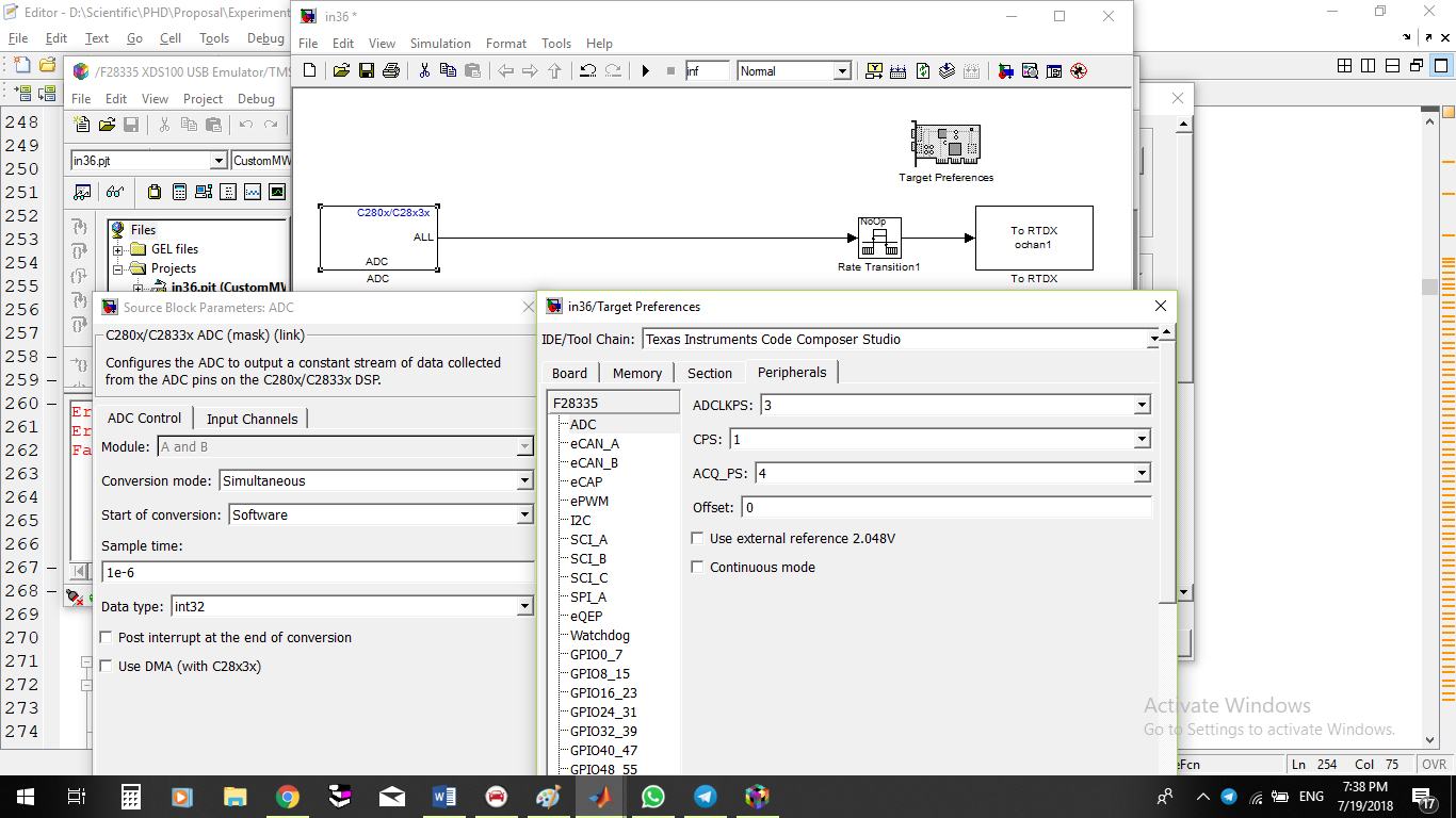
The following picture shows ADC0 that had to be a sinusoidal waveform. The second picture shows settings in Matlab/Simulink.  When I had only one ADC the data were more smooth and more similar to a sinusoidal waveform.

I'll appreciate if someone guides me on how can I have a more smooth waveform.

Best Regards, 

Abolfazl

  • Abolfazl,
    Thanks for reaching out to the E2E forum. From the pictures it looks like you have enabled simultaneous sampling; this will effectively half your sample rate on a given channel(it increases the throughput overall for the system). Can you describe your input/system a bit more; for example how many physical analog inputs do you have coming into the F2833x MCU? We also need to see how the MAXCONV is being set up by the GUI, as that can make alot of difference in the effective sample rate.

    Matt
  • Thank you MatthewPate for your respons.

    I wrapped the connecting cables with Aliminium sheets and the response is a little bit better (because of noise cansellation). But the sampling rate problem is not fixed yet. If I want to explane my work here I can say I'm reading data with ADC channels. Using a GUI interdace I transfer them from CCS to Matlab . Then Using "set_param" command I transfer them to my model in Simulink.


    I'm reading all 16 ADCs that contains 4 voltages, 3 currents, 2 torques, ... . I enabled simulataneous sampling. Since I'm not much familiar with this issue, I copy here all codes that generated with Matlab that exist in "c28xx_csl.c", "c28xx_board.c ","c28xx_adc.c","main.c " and "test.c" files.
    ==================================================
    c28xx_csl.c file :

    #include "DSP2833x_Device.h"
    #include "DSP2833x_GlobalPrototypes.h"
    #include "rtwtypes.h"
    #include "in36_test.h"
    #include "in36_test_private.h"

    void rt_OneStep(void);
    extern interrupt void datalog_isr (void);

    /*-----------------------------------------------------------------------------
    * void config_schedulerTimer(void)
    *
    * Abstract:
    * This function configures scheduler timer
    */
    void config_schedulerTimer(void)
    {
    InitCpuTimers();

    /* Configure CPU-Timer 0 to interrupt every 1.0E-5 sec. */
    /* Parameters: Timer Pointer, CPU Freq in MHz, Period in usec. */
    ConfigCpuTimer(&CpuTimer0, 150.0, 1.0E-5 * 1000000);
    StartCpuTimer0();
    }

    void disableWatchdog(void)
    {
    int *WatchdogWDCR = (void *) 0x7029;
    asm(" EALLOW ");
    *WatchdogWDCR = 0x0068;
    asm(" EDIS ");
    }

    interrupt void TINT0_isr(void)
    {
    volatile unsigned int PIEIER1_stack_save = PieCtrlRegs.PIEIER1.all;
    PieCtrlRegs.PIEIER1.all &= ~64; /*disable group1 lower/equal priority interrupts*/
    asm(" RPT #5 || NOP"); /*wait 5 cycles */
    IFR &= ~1; /*eventually disable lower/equal priority pending interrupts*/
    PieCtrlRegs.PIEACK.all = 1; /*ACK to allow other interrupts from the same group to fire*/
    IER |= 1;
    EINT; /*global interrupt enable*/
    rt_OneStep();
    DINT; /* disable global interrupts during context switch, CPU will enable global interrupts after exiting ISR */
    PieCtrlRegs.PIEIER1.all = PIEIER1_stack_save;/*restore PIEIER register that was modified*/
    }

    void enable_interrupts()
    {
    EALLOW;
    PieVectTable.DATALOG = &datalog_isr; /* Hook RTDX interrupt to the default ISR*/
    EDIS;
    IER |= M_DLOG; /* Enable CPU DLOG interrupt:*/
    EALLOW;
    PieVectTable.TINT0 = &TINT0_isr; /* Hook interrupt to the ISR*/
    EDIS;
    PieCtrlRegs.PIEIER1.bit.INTx7 = 1; /* Enable interrupt TINT0*/
    IER |= M_INT1;

    /* Enable global Interrupts and higher priority real-time debug events:*/
    EINT; /* Enable Global interrupt INTM*/
    ERTM; /* Enable Global realtime interrupt DBGM*/
    }

    void disable_interrupts()
    {
    IER &= M_INT1; /* Disable Global INT1 (CPU Interrupt 1)*/
    DINT; /* Disable Global interrupt INTM*/
    }


    ==========================================================
    c28xx_board.c file:

    #include "DSP2833x_Device.h"
    #include "DSP2833x_GlobalPrototypes.h"
    #include "rtwtypes.h"
    #include "in36_test.h"
    #include "in36_test_private.h"

    void InitXintf16Gpio();
    void init_board ()
    {
    DisableDog();

    /* Initialize the PLL control: PLLCR and DIVSEL
    * DSP28_PLLCR and DSP28_DIVSEL are defined in DSP2833x_Examples.h
    */
    InitPll(10,2);
    InitPeripheralClocks();
    EALLOW;

    /* Perform additional configuration of the XTINF for speed up */
    XintfRegs.XINTCNF2.bit.XTIMCLK = 0; /* XTIMCLK=SYSCLKOUT/1*/
    XintfRegs.XINTCNF2.bit.CLKOFF = 0; /* XCLKOUT is enabled*/
    XintfRegs.XINTCNF2.bit.CLKMODE = 0; /* XCLKOUT = XTIMCLK*/

    /* Make sure write buffer is empty before configuring buffering depth*/
    while (XintfRegs.XINTCNF2.bit.WLEVEL != 0) ;/* poll the WLEVEL bit*/
    XintfRegs.XINTCNF2.bit.WRBUFF = 0; /* No write buffering*/

    /* Example: Assume Zone 7 is slow, so add additional BCYC cycles whenever
    * switching from Zone 7 to another Zone. This will help avoid bus contention.
    */
    XintfRegs.XBANK.bit.BCYC = 3; /* Add 7 cycles*/
    XintfRegs.XBANK.bit.BANK = 3; /* select zone 7*/

    /* Zone 0 Configuration */
    XintfRegs.XTIMING0.bit.X2TIMING = 0; /* Timing scale factor = 1*/
    XintfRegs.XTIMING0.bit.XSIZE = 3; /* Always write as 11b*/
    XintfRegs.XTIMING0.bit.READYMODE = 1;/* XREADY is asynchronous*/
    XintfRegs.XTIMING0.bit.USEREADY = 0; /* Disable XREADY*/
    XintfRegs.XTIMING0.bit.XRDLEAD = 1; /* Read lead time*/
    XintfRegs.XTIMING0.bit.XRDACTIVE = 2;/* Read active time*/
    XintfRegs.XTIMING0.bit.XRDTRAIL = 1; /* Read trail time*/
    XintfRegs.XTIMING0.bit.XWRLEAD = 1; /* Write lead time*/
    XintfRegs.XTIMING0.bit.XWRACTIVE = 2;/* Write active time*/
    XintfRegs.XTIMING0.bit.XWRTRAIL = 1; /* Write trail time*/

    /* Zone 6 Configuration */
    XintfRegs.XTIMING6.bit.X2TIMING = 0; /* Timing scale factor = 1*/
    XintfRegs.XTIMING6.bit.XSIZE = 3; /* Always write as 11b*/
    XintfRegs.XTIMING6.bit.READYMODE = 1;/* XREADY is asynchronous*/
    XintfRegs.XTIMING6.bit.USEREADY = 0; /* Disable XREADY*/
    XintfRegs.XTIMING6.bit.XRDLEAD = 1; /* Read lead time*/
    XintfRegs.XTIMING6.bit.XRDACTIVE = 2;/* Read active time*/
    XintfRegs.XTIMING6.bit.XRDTRAIL = 1; /* Read trail time*/
    XintfRegs.XTIMING6.bit.XWRLEAD = 1; /* Write lead time*/
    XintfRegs.XTIMING6.bit.XWRACTIVE = 2;/* Write active time*/
    XintfRegs.XTIMING6.bit.XWRTRAIL = 1; /* Write trail time*/

    /* Zone 7 Configuration */
    XintfRegs.XTIMING7.bit.X2TIMING = 0; /* Timing scale factor = 1*/
    XintfRegs.XTIMING7.bit.XSIZE = 3; /* Always write as 11b*/
    XintfRegs.XTIMING7.bit.READYMODE = 1;/* XREADY is asynchronous*/
    XintfRegs.XTIMING7.bit.USEREADY = 0; /* Disable XREADY*/
    XintfRegs.XTIMING7.bit.XRDLEAD = 1; /* Read lead time*/
    XintfRegs.XTIMING7.bit.XRDACTIVE = 2;/* Read active time*/
    XintfRegs.XTIMING7.bit.XRDTRAIL = 1; /* Read trail time*/
    XintfRegs.XTIMING7.bit.XWRLEAD = 1; /* Write lead time*/
    XintfRegs.XTIMING7.bit.XWRACTIVE = 2;/* Write active time*/
    XintfRegs.XTIMING7.bit.XWRTRAIL = 1; /* Write trail time*/
    EDIS;
    InitXintf16Gpio();

    /* Flush pipeline to ensure that the write is complete. Wait to be sure. */
    asm(" RPT #6 || NOP");

    /* Disable and clear all CPU interrupts */
    DINT;
    IER = 0x0000;
    IFR = 0x0000;
    InitPieCtrl();
    InitPieVectTable();

    /* initial SPI function.... */
    InitCpuTimers();

    /* initial GPIO qualification settings.... */
    EALLOW;
    GpioCtrlRegs.GPAQSEL1.all = 0U;
    GpioCtrlRegs.GPAQSEL2.all = 0U;
    GpioCtrlRegs.GPBQSEL1.all = 0U;
    GpioCtrlRegs.GPBQSEL2.all = 0U;
    EDIS;
    }

    void InitXintf16Gpio()
    {
    EALLOW;
    GpioCtrlRegs.GPCMUX1.bit.GPIO64 = 3; /* XD15*/
    GpioCtrlRegs.GPCMUX1.bit.GPIO65 = 3; /* XD14*/
    GpioCtrlRegs.GPCMUX1.bit.GPIO66 = 3; /* XD13*/
    GpioCtrlRegs.GPCMUX1.bit.GPIO67 = 3; /* XD12*/
    GpioCtrlRegs.GPCMUX1.bit.GPIO68 = 3; /* XD11*/
    GpioCtrlRegs.GPCMUX1.bit.GPIO69 = 3; /* XD10*/
    GpioCtrlRegs.GPCMUX1.bit.GPIO70 = 3; /* XD19*/
    GpioCtrlRegs.GPCMUX1.bit.GPIO71 = 3; /* XD8*/
    GpioCtrlRegs.GPCMUX1.bit.GPIO72 = 3; /* XD7*/
    GpioCtrlRegs.GPCMUX1.bit.GPIO73 = 3; /* XD6*/
    GpioCtrlRegs.GPCMUX1.bit.GPIO74 = 3; /* XD5*/
    GpioCtrlRegs.GPCMUX1.bit.GPIO75 = 3; /* XD4*/
    GpioCtrlRegs.GPCMUX1.bit.GPIO76 = 3; /* XD3*/
    GpioCtrlRegs.GPCMUX1.bit.GPIO77 = 3; /* XD2*/
    GpioCtrlRegs.GPCMUX1.bit.GPIO78 = 3; /* XD1*/
    GpioCtrlRegs.GPCMUX1.bit.GPIO79 = 3; /* XD0*/
    GpioCtrlRegs.GPBMUX1.bit.GPIO40 = 3; /* XA0/XWE1n*/
    GpioCtrlRegs.GPBMUX1.bit.GPIO41 = 3; /* XA1*/
    GpioCtrlRegs.GPBMUX1.bit.GPIO42 = 3; /* XA2*/
    GpioCtrlRegs.GPBMUX1.bit.GPIO43 = 3; /* XA3*/
    GpioCtrlRegs.GPBMUX1.bit.GPIO44 = 3; /* XA4*/
    GpioCtrlRegs.GPBMUX1.bit.GPIO45 = 3; /* XA5*/
    GpioCtrlRegs.GPBMUX1.bit.GPIO46 = 3; /* XA6*/
    GpioCtrlRegs.GPBMUX1.bit.GPIO47 = 3; /* XA7*/
    GpioCtrlRegs.GPCMUX2.bit.GPIO80 = 3; /* XA8*/
    GpioCtrlRegs.GPCMUX2.bit.GPIO81 = 3; /* XA9*/
    GpioCtrlRegs.GPCMUX2.bit.GPIO82 = 3; /* XA10*/
    GpioCtrlRegs.GPCMUX2.bit.GPIO83 = 3; /* XA11*/
    GpioCtrlRegs.GPCMUX2.bit.GPIO84 = 3; /* XA12*/
    GpioCtrlRegs.GPCMUX2.bit.GPIO85 = 3; /* XA13*/
    GpioCtrlRegs.GPCMUX2.bit.GPIO86 = 3; /* XA14*/
    GpioCtrlRegs.GPCMUX2.bit.GPIO87 = 3; /* XA15*/
    GpioCtrlRegs.GPBMUX1.bit.GPIO39 = 3; /* XA16*/
    GpioCtrlRegs.GPAMUX2.bit.GPIO31 = 3; /* XA17*/
    GpioCtrlRegs.GPAMUX2.bit.GPIO30 = 3; /* XA18*/
    GpioCtrlRegs.GPAMUX2.bit.GPIO29 = 3; /* XA19*/
    GpioCtrlRegs.GPBMUX1.bit.GPIO34 = 3; /* XREADY*/
    GpioCtrlRegs.GPBMUX1.bit.GPIO35 = 3; /* XRNW*/
    GpioCtrlRegs.GPBMUX1.bit.GPIO38 = 3; /* XWE0*/
    GpioCtrlRegs.GPBMUX1.bit.GPIO36 = 3; /* XZCS0*/
    GpioCtrlRegs.GPBMUX1.bit.GPIO37 = 3; /* XZCS7*/
    GpioCtrlRegs.GPAMUX2.bit.GPIO28 = 3; /* XZCS6*/
    EDIS;
    }


    ==============================================
    c28xx_adc.c file:

    #include "DSP2833x_Device.h"
    #include "DSP2833x_GlobalPrototypes.h"
    #include "rtwtypes.h"
    #include "in36_test.h"
    #include "in36_test_private.h"

    void config_ADC_A(uint16_T maxConv, uint16_T adcChselSEQ1Reg, uint16_T
    adcChselSEQ2Reg, uint16_T adcChselSEQ3Reg, uint16_T
    adcChselSEQ4Reg)
    {
    AdcRegs.ADCTRL1.bit.SUSMOD = 0x0; /* Emulation suspend ignored*/
    AdcRegs.ADCTRL1.bit.ACQ_PS = 1; /* Acquisition window size*/
    AdcRegs.ADCTRL1.bit.CPS = 1; /* Core clock pre-scaler*/
    AdcRegs.ADCTRL3.bit.ADCCLKPS = 2; /* Core clock divider*/
    AdcRegs.ADCREFSEL.bit.REF_SEL = 0 ; /* Set Reference Voltage*/
    AdcRegs.ADCOFFTRIM.bit.OFFSET_TRIM = 0;/* Set Offset Error Correctino Value*/
    AdcRegs.ADCTRL1.bit.CONT_RUN = 0; /* 0:Start-Stop or continuous sequencer mode*/
    AdcRegs.ADCTRL3.bit.ADCBGRFDN = 0x3; /* Bandgap and reference powered up*/
    AdcRegs.ADCTRL3.bit.SMODE_SEL = 1 ; /* 1:Simultaneous, 0:Sequential sampling*/
    AdcRegs.ADCMAXCONV.bit.MAX_CONV1 = maxConv;/* Number of conversions in CONV2 when using B module*/
    AdcRegs.ADCTRL1.bit.SEQ_CASC = 1; /* 1:Cascaded, 0:Dual sequencer mode*/
    AdcRegs.ADCCHSELSEQ1.all = adcChselSEQ1Reg;/* Channels for conversion*/
    AdcRegs.ADCCHSELSEQ2.all = adcChselSEQ2Reg;/* Channels for conversion*/
    AdcRegs.ADCCHSELSEQ3.all = adcChselSEQ3Reg;/* Channels for conversion*/
    AdcRegs.ADCCHSELSEQ4.all = adcChselSEQ4Reg;/* Channels for conversion*/
    AdcRegs.ADCTRL2.bit.INT_MOD_SEQ1 = 0;
    AdcRegs.ADCTRL2.bit.INT_ENA_SEQ1 = 1;
    AdcRegs.ADCTRL2.bit.RST_SEQ1 = 0x1; /* Reset SEQ1*/
    }

    =============================================================================
    main.c file

    /*
    * File: in36_test_main.c
    *
    * Code generated for Simulink model 'in36_test'.
    *
    * Model version : 1.48
    * Simulink Coder version : 8.2 (R2012a) 29-Dec-2011
    * TLC version : 8.2 (Dec 29 2011)
    * C/C++ source code generated on : Sun Jul 22 11:20:09 2018
    *
    * Target selection: idelink_ert.tlc
    * Embedded hardware selection: Texas Instruments->C2000
    * Code generation objectives: Unspecified
    * Validation result: Not run
    */

    #include "in36_test.h"
    #include "rtwtypes.h"
    #include "in36_test_private.h"
    #include "c2000_main.h"
    #include "DSP2833x_Device.h"
    #include "DSP2833x_Examples.h"
    #include <stdlib.h>
    #include <stdio.h>

    void init_board(void);
    void enable_interrupts(void);
    void config_schedulerTimer(void);
    void disable_interrupts(void);
    volatile int IsrOverrun = 0;
    static boolean_T OverrunFlag = 0;

    /* Function: rt_OneStep -------------------------------------------
    *
    * Abstract:
    * Perform one step of the model. Single-tasking implementation.
    */
    void rt_OneStep(void)
    {
    /* Check for overrun. Protect OverrunFlag against
    * preemption.
    */
    if (OverrunFlag++) {
    IsrOverrun = 1;
    OverrunFlag--;
    return;
    }

    asm(" SETC INTM");
    PieCtrlRegs.PIEIER1.all |= (1 << 6);
    asm(" CLRC INTM");
    in36_test_step();

    /* Get model outputs here */
    asm(" SETC INTM");
    PieCtrlRegs.PIEIER1.all &= ~(1 << 6);
    asm(" RPT #5 || NOP");
    IFR &= 0xFFFE;
    PieCtrlRegs.PIEACK.all = 0x1;
    asm(" CLRC INTM");
    OverrunFlag--;
    }

    /* Function: main -------------------------------------------
    *
    * Abstract:
    * Entry point into the code.
    */
    void main(void)
    {
    volatile boolean_T noErr;
    init_board();
    rtmSetErrorStatus(in36_test_M, 0);
    in36_test_initialize();
    config_schedulerTimer();
    noErr =
    rtmGetErrorStatus(in36_test_M) == (NULL);
    enable_interrupts();
    while (noErr ) {
    noErr =
    rtmGetErrorStatus(in36_test_M) == (NULL);
    }

    /* Disable rt_OneStep() here */

    /* Terminate model */
    in36_test_terminate();
    disable_interrupts();
    }

    /*
    * File trailer for generated code.
    *
    * [EOF]
    */
    ===============================================================================
    .c file :


    /*
    * File: in36_test.c
    *
    * Code generated for Simulink model 'in36_test'.
    *
    * Model version : 1.48
    * Simulink Coder version : 8.2 (R2012a) 29-Dec-2011
    * TLC version : 8.2 (Dec 29 2011)
    * C/C++ source code generated on : Sun Jul 22 09:46:48 2018
    *
    * Target selection: idelink_ert.tlc
    * Embedded hardware selection: Texas Instruments->C2000
    * Code generation objectives: Unspecified
    * Validation result: Not run
    */

    #include "in36_test.h"
    #include "in36_test_private.h"

    RTDX_CreateOutputChannel(ochan1); /* Channel ochan1 for block <Root>/To RTDX */

    /* Block signals (auto storage) */
    BlockIO_in36_test in36_test_B;

    /* Real-time model */
    RT_MODEL_in36_test in36_test_M_;
    RT_MODEL_in36_test *const in36_test_M = &in36_test_M_;

    /* Model step function */
    void in36_test_step(void)
    {
    /* S-Function Block: <Root>/ADC (c280xadc) */
    {
    AdcRegs.ADCTRL2.bit.RST_SEQ1 = 1; /* Reset SEQ1 module*/
    AdcRegs.ADCST.bit.INT_SEQ1_CLR = 1;/*clear INT sequencer*/
    AdcRegs.ADCTRL2.bit.SOC_SEQ1 = 1; /* Software Trigger*/
    while (AdcRegs.ADCST.bit.INT_SEQ1 == 0) {
    } /*Wait for Sequencer INT bit to clear */

    asm(" RPT #11 || NOP");
    in36_test_B.ADC[0] = (AdcRegs.ADCRESULT0) >> 4;
    in36_test_B.ADC[1] = (AdcRegs.ADCRESULT1) >> 4;
    }

    /* S-Function Block: <Root>/To RTDX (rtdx_snk) */
    if (RTDX_isOutputEnabled( &ochan1 )) {
    while (RTDX_writing != NULL) {
    } /* waiting for rtdx write to complete */

    RTDX_write( &ochan1, (void*) in36_test_B.ADC, 2*sizeof(int32_T));
    }
    }

    /* Model initialize function */
    void in36_test_initialize(void)
    {
    /* Registration code */

    /* initialize error status */
    rtmSetErrorStatus(in36_test_M, (NULL));

    /* block I/O */
    (void) memset(((void *) &in36_test_B), 0,
    sizeof(BlockIO_in36_test));

    /* Start for S-Function (c280xadc): '<Root>/ADC' */
    InitAdc();
    config_ADC_A (0U, 0U, 0U, 0U, 0U);

    /* Start for S-Function (rtdx_snk): '<Root>/To RTDX' */
    RTDX_enableOutput(&ochan1); /* S-Function Block: <Root>/To RTDX (rtdx_snk) */
    }

    /* Model terminate function */
    void in36_test_terminate(void)
    {
    /* Terminate for S-Function (rtdx_snk): '<Root>/To RTDX' */
    RTDX_disableOutput(&ochan1); /* S-Function Block: <Root>/To RTDX (rtdx_snk) */
    }

    /*
    * File trailer for generated code.
    *
    * [EOF]
    */


    =================================================================
    Hope to hear from you soon.
    Kind Regards,
    Abolfazl
  • Abolfazl,

    For best speed, we need to make sure the ADC Clock is 25MHz and ACQPS = 0.  The current setting for ACQPS = 4, so that can be changed to 0 easily.

    Determining the ADC clock will be a bit more involved; there are 2 fields you are showing, the CPS bit and the ADCCLKPS bits.  However, we also need to know the HSPCLK divider.  This register is located in the system control space, with the PLL.  In most cases, HSPCLK is set to 3(which gives a div by 6) and that will give 25MHz to the ADC.  In this case you can then zero out the ADCCLKPS and CPS bits.

    Due to the pipeline architecture of the ADC on this device, any time we start/stop the ADC we absorb a cycle hit until the ADC is converting continuously.  So, I would recommend setting the cont run bit for best throughput if possible, else you will absorb an additional 40ns for each run(which may be OK for your system)  

    At any rate the sample timings for your use case are listed here :http://www.ti.com/product/TMS320F28335/datasheet/specifications#sprs2301242  

    If we keep the ADC loaded, then you should get 2 results every 120ns, or 16.67MSPS.  If I further define this as the sample rate of each input(since you are using all 16) then each signal will be sampled at ~1.04MSPS

    Best,

    Matthew

  • Dear Matthew,

    Thank you for your comprehensive response. I changed the  ACQPS to zero but it didn't make any difference. 

    Now I think maybe the problem is because of RTDX. As I read in " " RTDX is available on XDS510 and XDS560 class of emulators but I have a TMS320F28335 Experimenter Kit with XDS100 emulator. Do you have any idea about it?

    Bests,

    Abolfazl

  • Abolfazl,
    While the comment on RTDX support by emulator is correct, I'm not certain that block is being used. I say this because you are getting ADC data inside of simulink. I'm going to get some more folks looking at this who are more simulink savvy than myself.

    Matt