This thread has been locked.

If you have a related question, please click the "Ask a related question" button in the top right corner. The newly created question will be automatically linked to this question.

TMS320F28035: Read and write operation using EEPROM through I2C

Part Number: TMS320F28035
Other Parts Discussed in Thread: C2000WARE

Hello,

I am developing a Battery Management System using TMS320F28035 as microcontroller and the combo bq7694000DBT + BQ78350DBTR-R1. We have already developed a BMS version employing MSP430, and it works fine, thanks to all examples and experts which answered all our questions.

After testing CAN bus network, at this point of the project the next step is to develop an I2C interface. For this task, I am taking the example "Example_2803xI2C_eeprom.c" and some information at this thread (https://e2e.ti.com/support/microcontrollers/c2000/f/171/t/303750?tisearch=e2e-quicksearch&keymatch=i2c%20read#pi316717=3) as resource of information.

We divided the test into three steps:

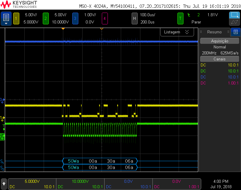
1-) Write operation to a EEPROM 24LC32AT-I/SN from Microchip (figure below). It seems it is working properly as I can write multiple times.

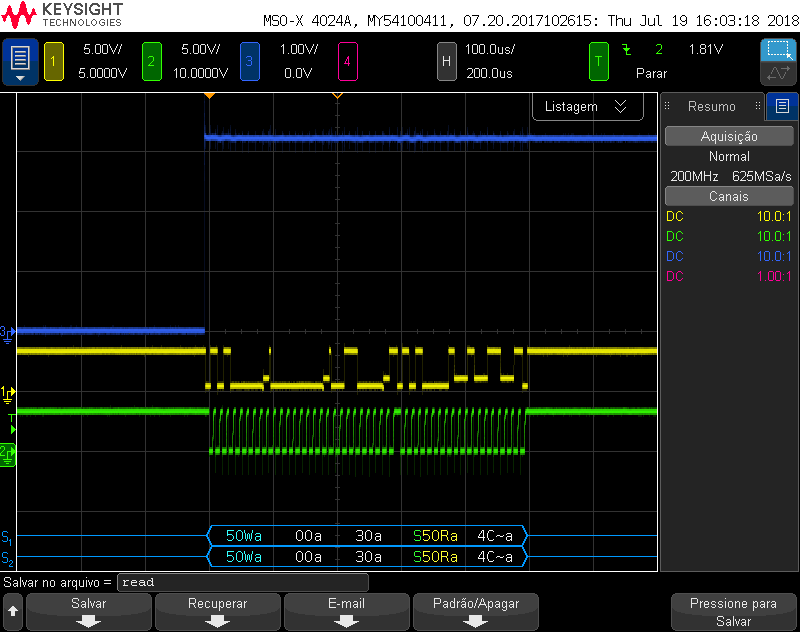
2-) Read operation to the same EEPROM memory. It seems it is working properly as well. The retrieved data is different because it is a counter.

3-) Write and read operation after writing. At this point the issues arise. I cannot be able to write and read, because it seems the programm is stuck at read function. I have already read I2C registers documentation and examples stated above, as well , and I was not able to find the issue. It seems I did not clear some flag or something like that.

I have attached the code. Please, could someone help on this issue?

Thank you in advance.

Desktop.rar

  • Hi Felipe,

    For the issue you're seeing you say it gets stuck in the read function, so it never returns? Can you see where it gets stuck while debugging? You might need to turn off FREE mode using the I2CMDR register within your read function to successfully debug. Are you not seeing anything on the scope after the write function? Might help in debugging to check the I2CSTR (status register) within the expressions window of ccs after the write function and at different points of your read function.

    For your write then read test, are you performing the following?

            Error = I2CA_WriteData(&I2cMsgOut1);
    
            Error = I2CA_ReadData(&I2cMsgIn1);

    Best,

    Kevin

  • Hello Kevin,

    Thank you for replying me.

    Yes, I am performing the above procedure to write and read.

    Watchig I2C register, when trying to read, the I2C status register content is 0x0410. According to the datasheet, this register value means there is no underflow detected, at the same time the data has been copied from I2CDXR to I2CXSR. Assuming the I2C is not under reset condition, does it mean it is waiting another load to I2CDXR register?

    Best regards,

    Felipe.


  • When just reading, the I2C status register content is 0x2410.
  • Hi Felipe,

    So the only difference is the NACK sent bit. Should have mentioned this earlier, but it'd be useful to check the value of the I2CMDR register before & after reading for both cases (I.E. after writing and when only reading). Maybe the bus is busy?

    I2caRegs.I2CSTR.bit.BB == 1

    In your code the read/write functions return errors, but there is no error checking within the main loop. Are there any errors occurring within the read/write functions? Are there any waveforms you can see when performing a read after writing? I probably need to run the example program again and look at the resulting waveforms, but I believe you have to attempt reading the EEPROM address multiple times before succeeding while you only have one attempt occurring.

    Best,

    Kevin

  • Hello Kevin,

    After some tests, popably the bus is busy as you mencioned. I changed the code a little bit, and, putting some breakpoints at the main function (after writing and after readind functions), and I was able to see both waveforms perfectly, exactly as expected. But, if I remove the breakpoints, the code just write, like before. It seems there is some flag or status preventing the correctly bus function.

    So, I did a delay function, which needs some adjustment, in put it before ending both write and read functions. It is not an elegant  approach, but is working. I am not sure if in the final project I need this task (writng and reading in sequence), but, at least I have this option.

    Do you need is there a better approach?

    I also attached the new code.

    Greetings,

    Felipe.

    BMS_v3.rar

  • Hi Felipe,

    Yes, it's likely that the initial write communication is not yet completed and the I2C peripheral is getting confused. I'd suggest looking at how the Example_2803xI2C_eeprom example program within C2000Ware handles its communication using the CurrentMsgPtr->MsgStatus.

    Your read function is probably producing an error somewhere within it. You should probably implement some sort of error checking/handling code. I could see one of the two checks below triggering:

        //
        // Wait until STP bit is cleared from any previous master communication.
        // Clearing of this bit by the module is delayed until after the SCD bit is
        // set. If this bit is not checked prior to initiating a new message, the
        // I2C could get confused.
        //
        if (I2caRegs.I2CMDR.bit.STP == 1)
        {
          return I2C_STP_NOT_READY_ERROR;
        }
    
        //
        // Check if bus busy
        //
        if (I2caRegs.I2CSTR.bit.BB == 1)
        {
            return I2C_BUS_BUSY_ERROR;
        }

    Hope this helps,

    Kevin

  • Hello Kevin,

    I followed your sugestion, and I got the waveform below. In order to verify if the write time is correct (ate least, in the same order of magnitude), I read the memory datasheet and found the maximum write time cycle is 5 ms, which is in agreement with the waveform. Do you believe this assuption is correct?


    As we can see, the controller writes the data, and tries to read it back. It tries several times before it gets it back. After that, it verifies if the recovered data is equal to the sent one. If it is, it stops the programm using the pass() function. I read the firmware and looked for some document, but I am not sure if it is what is expected. Do you know if this is the correct firmware function?

    If it is correct, the next step is to use it for another device.

    Thank you for all the support.


  • Hi Felipe,

    Yes this all sounds right. I believe I lead you down the wrong direction earlier saying an error is likely occurring within your read function.

    The reason you couldn't immediately read memory from the eeprom is because the address setup portion was not successfully completed (I.E. the eeprom is not ready to send the requested data). As you mentioned the eeprom spec has a 5ms maximum write cycle time, so it can take up to 5s for the epprom to have the data ready to be sent to the f2803x master.

    If you're looking at the i2c_eeprom program example the I2CA_ReadData function waits to read from memory until the I2C_MSGSTAT_RESTART status is established:

        else if(msg->MsgStatus == I2C_MSGSTAT_RESTART)
        {
            I2caRegs.I2CCNT = msg->NumOfBytes;  // Setup how many bytes to expect
            I2caRegs.I2CMDR.all = 0x2C20;       // Send restart as master receiver
        }
        return I2C_SUCCESS;

    This status is established within the i2c_int1a_isr once the I2C_ARDY_ISRC (Registers ready to be accessed) interrupt source code is seen:

        //
        // Interrupt source = Register Access Ready
        // This interrupt is used to determine when the EEPROM address setup 
        // portion of the read data communication is complete. Since no stop bit is
        // commanded, this flag tells us when the message has been sent instead of 
        // the SCD flag. If a NACK is received, clear the NACK bit and command a 
        // stop. Otherwise, move on to the read data portion of the communication.
        //
        else if(IntSource == I2C_ARDY_ISRC)
        {
            if(I2caRegs.I2CSTR.bit.NACK == 1)
            {
                I2caRegs.I2CMDR.bit.STP = 1;
                I2caRegs.I2CSTR.all = I2C_CLR_NACK_BIT;
            }
            else if(CurrentMsgPtr->MsgStatus == I2C_MSGSTAT_SEND_NOSTOP_BUSY)
            {
                CurrentMsgPtr->MsgStatus = I2C_MSGSTAT_RESTART;
            }
        }  

    Otherwise stop conditions are being detected on each ReadData execution and the I2C_MSGSTAT_SEND_NOSTOP status is maintained, which causes the eeprom setup portion within the ReadData function to keep being run each time:

        //
        // Interrupt source = stop condition detected
        //
        if(IntSource == I2C_SCD_ISRC)
        {
            ...
                //
                // If a message receives a NACK during the address setup portion 
                // of the EEPROM read, the code further below included in the 
                // register access ready interrupt source code will generate a stop
                // condition. After the stop condition is received (here), set the 
                // message status to try again. User may want to limit the number 
                // of retries before generating an error.
                //
                if(CurrentMsgPtr->MsgStatus == I2C_MSGSTAT_SEND_NOSTOP_BUSY)
                {
                    CurrentMsgPtr->MsgStatus = I2C_MSGSTAT_SEND_NOSTOP;
                }
        }

    Hope this helps,

    Kevin

    Edit: Yes, your understanding of the pausing of the program with the pass() function after a successful read is correct. The example is designed to only read 2 bytes from the eeprom and then stop.

  • Hi Kevin,

    Thank you for all the support. This resolved my issue.

    Regards,

    Felipe.