This thread has been locked.

If you have a related question, please click the "Ask a related question" button in the top right corner. The newly created question will be automatically linked to this question.

TMS320F28335: internal ADCREFP looks like tooth wave

Part Number: TMS320F28335

Hi ,

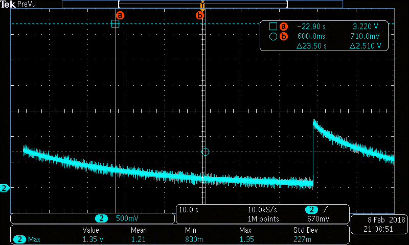
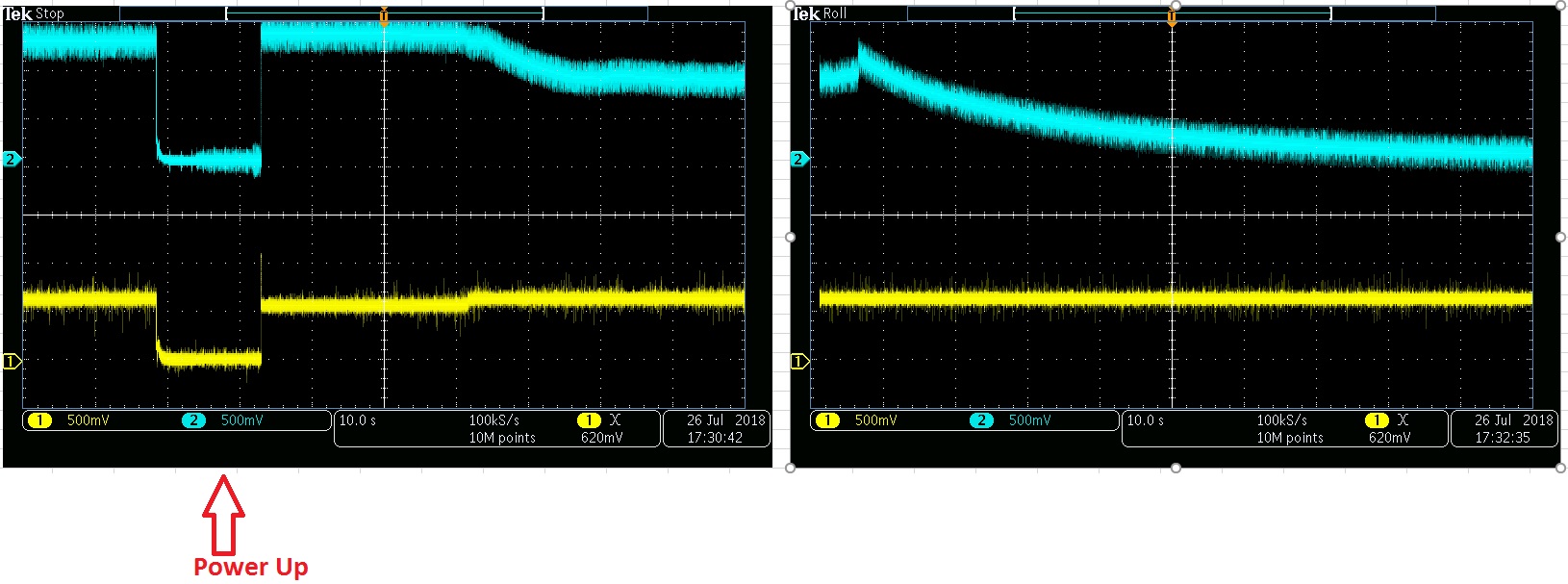
I measured tooth wave 0.1-- 1.35Volt , Period of 60-100 seconds on several 28335 DSPs  ADCREFP output.  

The issue occurred after 1 day of operation in one case  and  after 60 days in another .

The software is Ok. 

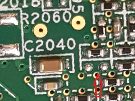
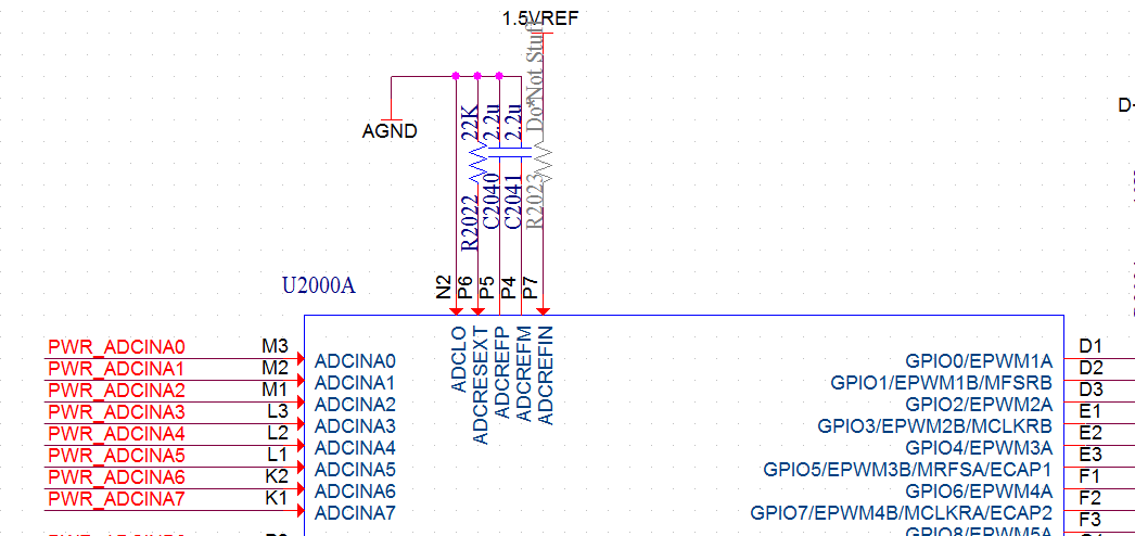
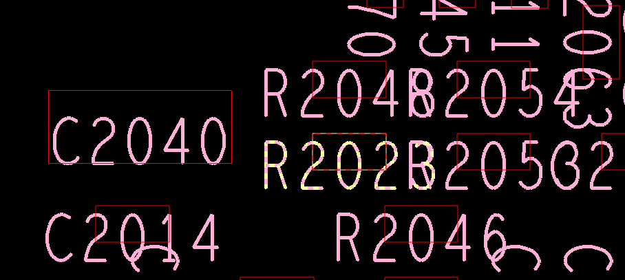
ADCREFIN was floated on this revision of PCBs.  ADCREFIN connecting to AGND with wire not helps.

Please advise.

  • Michael,

    Is this a custom PCB, or a TI EVM?  I would look to make sure the 2.2uF caps on ADCREFP(and M) are still good, or just replace them if possible to see if there is any change.  Also make sure that the 22kOhm resistor on ADCRESEXT is also OK.

    The period you are talking about is quite large, and something I don't expect to be generated by the MCU, even with ADCREFIN floating.  Can you also describe the conditions the boards were under before the failures occurred?

    Best,
    Matthew

  • Matthew,

    This is custom PCB.  I replaced 2.2uF and 22k Resistor , but ADCREFP is still the same . 

    Most of the boards are Ok during several years .

    I need to understand this issue for failure analysis . Do we need redesign PCB and connect  ADCRESEXT to AGND ?

    Thank you,

    Michael

  • The PCB was located outdoor in IP65 aluminium enclosure with ambient 25-50 degrees Celsius inside the box . One board stopped to work several hours after power up on customer site. Second after 60 days. I will try to find more boards with this symptom. I did X-RAY , but not found any problem with soldering.
  • Part Number: TMS320F28335

    Hi Team ,

        A huge AA customer had designed long ago a board using our TMS320F28335 witn an internal Vref for the ADC.

    They did not connect the ADCREFIn to GND (as they should have done) and just left this pin open.

    The board worked fine for long time in many systems.

    lately the had received few RMA units with ADC not working at all .They have identitied that the ADCREFIN pin is floating so when they connected it back to GND as it should have been from the start but the ADC still does not work.

    They are asking what can cause a failure of the ADC and if it is related to this ADCREFIN pin being floating on their board.

    Attached is the signal they see using an opscilloscope when this pin is floating plus partial schematic portion and the PCB layout in this section.

    Please advise them how to check why the ADC is still no0t working and what can be the long term impact of leaving the ADCREFIN floating as they did.

    Best regards ,

    Ariel Pickholz ,

    AFAE , Israel Sales

  • Michael,
    I just want to clarify one point:

    1)ADCREFIN currently is floating
    2)ADCRESEXT connected with 22kOhm resistor to ground.

    Please confirm the above.

    While it is best practice to tie unused ADCREFIN to ground, I do not believe floating the pin would cause this kind of issue.

    Can you also measure ADCREFM signal and note its behavior? On a scope both ADCREFP/ADCREFM should look very DC in nature; around 2V and 1V respectively.

    If you could attach a scope plot of the failing device that would help as well.

    Best,
    Matthew
  • Michael/Ariel,
    I've merged these threads as they are on the same topic. Ariel's post answers most of the questions I had for Michael so we can move on from that.

    Looking at the waveform we can see that ADCREFP begins to ramp up, then discharges over time.

    I think we may be looking at a symptom(rather than the root cause) of a system issue. I would suggest we put another scope probe on XRSn and see its behavior with ADCREFP. My theory is that the code on the MCU begins to run/initialize and is somehow interrupted/stopped by an XRSn event and we start over again.

    Given the size of the cap on ADCREFP this behavior is one I would expect if the enable bit inside the ADC registers is disabled. If possible I would connect an emulator to the device and enable the ADC manually (or run through the ADC setup code and halt), and see if the problem on ADCREFP goes away.

    Assuming both the above are true then we can debug the true root cause of the issue, again I suspect the device going into reset caused by something external.

    Finally, while the datasheet recommendation is to tie ADCREFIN to ground this is more a best practice to not float an unused pin for ESD reasons, etc. Certainly there is an increase in likelyhood an ESD event could could cause and over/under-voltage on this pin if it is floating, in which case there can be unpredictable damage. However, based on the behavior shown in the scope plots I can't conclude that is the root cause at this time.

    Ariel/Michael,
    If we think it would be helpful to have a call please let me know and we can get something setup off-forum.

    Best,
    Matthew
  • Hi , Matthew,Ariel

    ADCREFP and ADCREFM, looks like 2.2uF discharge via TPP0500B oscilloscope probe (10M).  Pressing  CPU case can restore the ADCREFP signal ( ADC still displays wrong results). So , it looks like cold solder contact , some capacitors crack , wirebond disconnect or similar.   Will check this next week.

    Thank you,

    Michael

  • Hi. Finally it was single ferrite bead to VDD1A18 and VDD2A18 microcrack (in 2 boards) . Pressing on CPU caused PCB deformation and restored ADCREFP . Bypassing of ferrite solved problem. . Than you , Michael