This thread has been locked.

If you have a related question, please click the "Ask a related question" button in the top right corner. The newly created question will be automatically linked to this question.

LAUNCHXL-F28027F: BLDC Motor shaft oscillation issue

Part Number: LAUNCHXL-F28027F
Other Parts Discussed in Thread: BOOSTXL-DRV8301, MOTORWARE

Hi Everyone,

I am trying to control the speed of a small Hobbyking BL1230 5300kv Brushless Inrunner Motor using an F28027F launchpad and a BOOSTXL-DRV8301. I am using the example Simulink model (45124) where a BLY172S-24V-4000 motor is used.

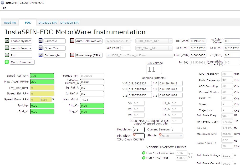
I was able to successfully run Lab2b through Motorware using the Universal GUI method and have obtained the motor identification parameters. I have also included these parameters in my Matlab setup file (c28027pmsmfoc_data) and I am able to successfully compile the code. However, the problem I am facing is that my motor shaft seems to be oscillating between two poles.

So far, I have reduced and eliminated the Kp & Ki gains in the Simulink Speed Controller Block and also the Sliding Mode Observer Gains (SMO) in the Matlab setup file. I am currently under the impression that the source of this problem is a setup/initialisation process that is unable to be completed? (Please correct me if I am wrong).

Has anyone experienced a similar problem with their motor before where the shaft continues to oscillate between two poles? Any help will be greatly appreciated.

Best Regards,

Riley

  • 1. You might use lab02c to identify the motor parameters since the motor maybe low inductance.
    2. You may disable the speed close loop first to check if the estimated angle of SMO is correct, maybe, you need to tune the control parameters of SMO, not the default parameters in Simulink.
  • Thanks for you reply,

    I have since run lab5b and after I ran the Identification I tried to adjust the Speed_Ref_RPM. The motor tried to start spinning; however, it stopped after a very short time (Different motion produced from Simulink example).

    I have run Lab02c and have tried to save my parameters into the User.h file and run Lab5b; however, I am still having the same issue as before.

    Here are the most recent results from a Lab02c motor identification using the UNIVERSAL GUI:

    The Motor stopped in the Ramp Up state (0.12A, ~2000rpm) and continued spinning again in the Rated flux state (0.14A, ~3500rpm) continuing on to complete the rest of the identification sequence.

    I am currently reading through the Sanity Checks provided in the UNIVERSAL GUI QSG to make the necessary adjustments.


    The details of my setup:


    Motor Specifications:

    Hobbyking BL1230 5300kv Brushless Inrunner Motor

    3s LiPo cells (11.1v)

    Max current (at 11.1V): 3 A

    Kv(rpm/v): 5300.00 (58,830rpm)


    I am currently using a benchtop power supply of 11.1v for DRV-8301 and here are all the changes I have made to the User.h file in CCS v8.


    //! \brief CURRENTS AND VOLTAGES

    // **************************************************************************

    #define USER_IQ_FULL_SCALE_FREQ_Hz     (1200)

    #define USER_IQ_FULL_SCALE_VOLTAGE_V   (11.1)

    #define USER_PWM_FREQ_kHz             (60.0)

    #define USER_R_OVER_L_EST_FREQ_Hz       (200)

    //! \brief USER MOTOR & ID SETTINGS

    // **************************************************************************

    #define USER_MOTOR_TYPE                 MOTOR_Type_Pm

    #define USER_MOTOR_NUM_POLE_PAIRS       (2)

    #define USER_MOTOR_Rr                   (NULL)

    #define USER_MOTOR_Rs                   (NULL)

    #define USER_MOTOR_Ls_d                 (NULL)

    #define USER_MOTOR_Ls_q                 (NULL)

    #define USER_MOTOR_RATED_FLUX           (NULL)

    #define USER_MOTOR_MAGNETIZING_CURRENT (NULL)

    #define USER_MOTOR_RES_EST_CURRENT     (0.3)

    #define USER_MOTOR_IND_EST_CURRENT     (-0.3)

    #define USER_MOTOR_MAX_CURRENT         (8.5)

    #define USER_MOTOR_FLUX_EST_FREQ_Hz     (120)

    Please let me know if you see any obvious mistakes I am making.


    Kind Regards,

    Riley

  • Hi Yanming, 

    I have stepped through the “Motor ID Tips” tuning suggestions, and the only way for the motors to complete the identifications is from changing the RES_EST_CURRENT from 0.3A to 0.85A. I realised I had forgotten to change these when I changed MOTOR_MAX_CURRENT from 3A to 8.5A.


    Here are my new settings that allow for a full completion of the motor identification cycle.

    //! \brief CURRENTS AND VOLTAGES

    // **************************************************************************

    #define USER_IQ_FULL_SCALE_FREQ_Hz     (986) //calculated from variables spreadsheet

    #define USER_IQ_FULL_SCALE_VOLTAGE_V   (11.1)

    #define USER_PWM_FREQ_kHz             (60.0)

    #define USER_R_OVER_L_EST_FREQ_Hz       (300)


    //! \brief USER MOTOR & ID SETTINGS

    // **************************************************************************

    #define USER_MOTOR_TYPE                 MOTOR_Type_Pm

    #define USER_MOTOR_NUM_POLE_PAIRS       (1) //Motor only has 2 poles

    #define USER_MOTOR_Rr                   (NULL)

    #define USER_MOTOR_Rs                   (NULL)

    #define USER_MOTOR_Ls_d                (NULL)

    #define USER_MOTOR_Ls_q                 (NULL)

    #define USER_MOTOR_RATED_FLUX           (NULL)

    #define USER_MOTOR_MAGNETIZING_CURRENT (NULL)

    #define USER_MOTOR_RES_EST_CURRENT     (0.85) //Required for RampUp completion

    #define USER_MOTOR_IND_EST_CURRENT     (-0.85)//10% of Max Current

    #define USER_MOTOR_MAX_CURRENT         (8.5)

    #define USER_MOTOR_FLUX_EST_FREQ_Hz     (90)  //From variables spreadsheet


    The results were as follows:

    The short circuit current seems to be quite large at 86.5A; however, the RS & flux variable are quite similar to my previous tests.        
    After I completed the Identification, I then transferred the parameters (including adc bias offsets) into User.h file and tried to run Lab05b; however, I could not enable the system to begin the lab.

    Do you know why I am unable to run this lab with my newly obtained parameters? Do you think it is related to the high Isc value?

    Kind Regards, 

    Riley

  • Is there any Error report in the CCS project or GUI? Like gMotorVars.UserErrorCode. You might follow instaSPIN lab guide to debug the project with CCS, not using the GUI which is good for demo or control, not tuning the design.

    I can't fully understand what you mean "the short circuit current seems to be quite large at 86.5A" and "high Isc value". It seemd like the motor didn't start running, and didn't have any feedback speed. Did you enable force angle in your project, is there any load on the motor during the startup? Please refer to section 14 of instaSPIN User's Guide ( SPRUHJ1G) for startup setting.

    Could you please post some motor current waveforms to show the running state, especially the motor stopped by some faults.
  • Just wanted to check in and see if there is any update from your side, I haven’t heard from you for two weeks, so I’m assuming you were able to resolve your issue. Please let me know if you have any questions. We would like to close this thread if no any further questions. Thanks.
  • Hi Yanming, 

    Apologies for my delayed response.

    I was primarily using the small motor as a test motor, as it was all i had at the time. I have since acquired a telco DT4260 motor instead for testing purposes and PI controller tuning. I have also moved to Simulink as i am more experienced with its environment and am able to meet my design objectives faster.

    Thanks for your help, appreciate it.

    Regards,

    Riley