Hi,
I'm using TMS320F28377D and I'm trying to configure ADC module. According to the datasheet and my own hardware, I assume that ACQPs minimum should be 201ns. I'm running at 150 MHz SYSCLK and 25 MHz ADC clock., so the register ACQPS should be around 30. The problem is that when I check the ADC results register I see that the ADC points are less than it should be. I've checked that the VERFHI voltage is 3V and VEREFLO is 0V (also checked the value in points is 0 converting channels 8 and 9 of ADC module B).
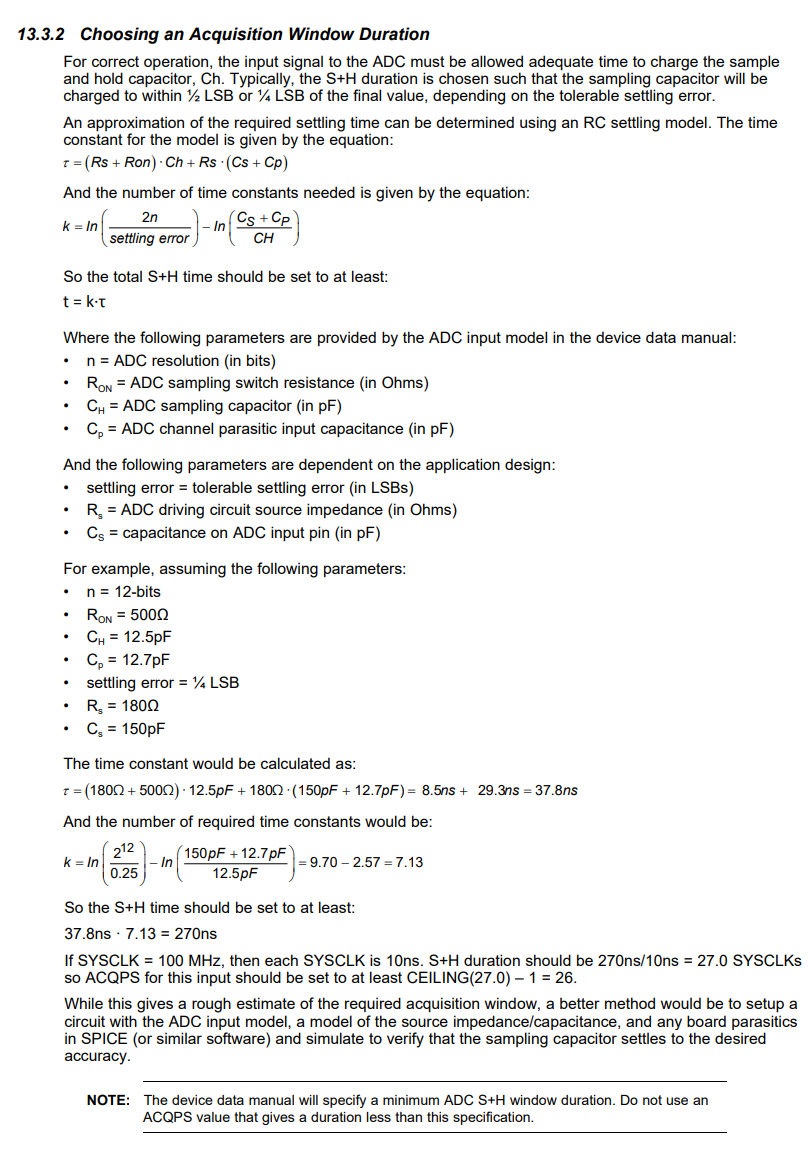
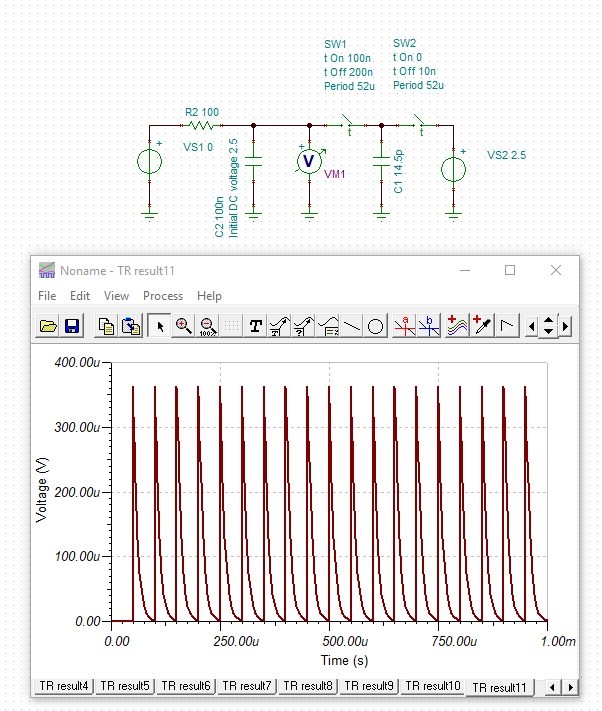
From the datasheet I know that sampling capacitor is 14.5pF, Rs = 450 Ohms and from my hardware I have an RC filter (R=1kOhm,C= 1nF). I attach here the circuit.

For example, if I have 1.5V (which are checked) measured in ADCINx, the value I get in points is 2031 instead of 2048. I think it is too much error. Then, if I set a bigger ACQPS value (at least 10 times bigger), I can reach 2048 points but the conversion time is too much for my application. I don't know why do I have too much error.
I'm using four ADC modules in order to do simultaneous sampling, with two different trigger (PWM1_SOCA_TRIGGER = zero, PWM1_SOB_TRIGGER = period). PWM1 runs at 57.6kHz (up&down). I generate this PWM_SOC's after 3 events, so the sampling is at 57.6kHz/3 = 19.2 kHz. Each module has 16 conversions, 8 with each trigger. The sampling window is the same for each SOC (except DSP internal temperature channel). At the EOC15 of ADC module, and interrupt is generated, which is the interrupt source for DMA module, where I use the ADC results for muy application.
Below there is the ADC setup code.
So, my question is. Why do I get this error in ADC conversion?
EALLOW;
//--- Reset the ADC. This is good programming practice.
DevCfgRegs.SOFTPRES13.bit.ADC_A = 1; // ADCA is reset
DevCfgRegs.SOFTPRES13.bit.ADC_B = 1; // ADCB is reset
DevCfgRegs.SOFTPRES13.bit.ADC_C = 1; // ADCC is reset
DevCfgRegs.SOFTPRES13.bit.ADC_D = 1; // ADCD is reset
DevCfgRegs.SOFTPRES13.bit.ADC_A = 0; // ADCA is released from reset
DevCfgRegs.SOFTPRES13.bit.ADC_B = 0; // ADCB is released from reset
DevCfgRegs.SOFTPRES13.bit.ADC_C = 0; // ADCC is released from reset
DevCfgRegs.SOFTPRES13.bit.ADC_D = 0; // ADCD is released from reset
//--- Configure the ADC base registers
AdcaRegs.ADCCTL1.all = 0x0004; // Main ADC configuration
AdcbRegs.ADCCTL1.all = 0x0004;
AdccRegs.ADCCTL1.all = 0x0004;
AdcdRegs.ADCCTL1.all = 0x0004;
AdcaRegs.ADCCTL2.all = 0x000A; // ADC clock configuration at 25MHz
AdcbRegs.ADCCTL2.all = 0x000A; // ADC clock configuration
AdccRegs.ADCCTL2.all = 0x000A; // ADC clock configuration
AdcdRegs.ADCCTL2.all = 0x000A; // ADC clock configuration
AdcaRegs.ADCBURSTCTL.all = 0x0000;
AdcbRegs.ADCBURSTCTL.all = 0x0000;
AdccRegs.ADCBURSTCTL.all = 0x0000;
AdcdRegs.ADCBURSTCTL.all = 0x0000;
//--- Call AdcSetMode() to configure the resolution and signal mode.
// This also performs the correct ADC calibration for the configured mode.
AdcSetMode(ADC_ADCA, ADC_RESOLUTION_12BIT, ADC_SIGNALMODE_SINGLE);
AdcSetMode(ADC_ADCB, ADC_RESOLUTION_12BIT, ADC_SIGNALMODE_SINGLE);
AdcSetMode(ADC_ADCC, ADC_RESOLUTION_12BIT, ADC_SIGNALMODE_SINGLE);
AdcSetMode(ADC_ADCD, ADC_RESOLUTION_12BIT, ADC_SIGNALMODE_SINGLE);
//--- SOCs configuration for all ADCs modules enabled
// Set minimum acquisition window (in SYSCLKS)
AdcaRegs.ADCSOC0CTL.bit.ACQPS = 30;
AdcaRegs.ADCSOC1CTL.bit.ACQPS = 30 ;
AdcaRegs.ADCSOC2CTL.bit.ACQPS = 30 ;
AdcaRegs.ADCSOC3CTL.bit.ACQPS = 30 ;
AdcaRegs.ADCSOC4CTL.bit.ACQPS = 30 ;
AdcaRegs.ADCSOC5CTL.bit.ACQPS = 30 ;
AdcaRegs.ADCSOC6CTL.bit.ACQPS = 104;
AdcaRegs.ADCSOC7CTL.bit.ACQPS = 30 ;
AdcaRegs.ADCSOC8CTL.bit.ACQPS = 30 ;
AdcaRegs.ADCSOC9CTL.bit.ACQPS = 30 ;
AdcaRegs.ADCSOC10CTL.bit.ACQPS = 30 ;
AdcaRegs.ADCSOC11CTL.bit.ACQPS = 30 ;
AdcaRegs.ADCSOC12CTL.bit.ACQPS = 30 ;
AdcaRegs.ADCSOC13CTL.bit.ACQPS = 30 ;
AdcaRegs.ADCSOC14CTL.bit.ACQPS = 104;
AdcaRegs.ADCSOC15CTL.bit.ACQPS = 30;
AdcbRegs.ADCSOC0CTL.bit.ACQPS = 30;
AdcbRegs.ADCSOC1CTL.bit.ACQPS = 30;
AdcbRegs.ADCSOC2CTL.bit.ACQPS = 30;
AdcbRegs.ADCSOC3CTL.bit.ACQPS = 30;
AdcbRegs.ADCSOC4CTL.bit.ACQPS = 30;
AdcbRegs.ADCSOC5CTL.bit.ACQPS = 30;
AdcbRegs.ADCSOC6CTL.bit.ACQPS = 30;
AdcbRegs.ADCSOC7CTL.bit.ACQPS = 30;
AdcbRegs.ADCSOC8CTL.bit.ACQPS = 30;
AdcbRegs.ADCSOC9CTL.bit.ACQPS = 30;
AdcbRegs.ADCSOC10CTL.bit.ACQPS = 30;
AdcbRegs.ADCSOC11CTL.bit.ACQPS = 30;
AdcbRegs.ADCSOC12CTL.bit.ACQPS = 30;
AdcbRegs.ADCSOC13CTL.bit.ACQPS = 30;
AdcbRegs.ADCSOC14CTL.bit.ACQPS = 30;
AdcbRegs.ADCSOC15CTL.bit.ACQPS = 30;
AdccRegs.ADCSOC0CTL.bit.ACQPS = 30;
AdccRegs.ADCSOC1CTL.bit.ACQPS = 30;
AdccRegs.ADCSOC2CTL.bit.ACQPS = 30;
AdccRegs.ADCSOC3CTL.bit.ACQPS = 30;
AdccRegs.ADCSOC4CTL.bit.ACQPS = 30;
AdccRegs.ADCSOC5CTL.bit.ACQPS = 30;
AdccRegs.ADCSOC6CTL.bit.ACQPS = 30;
AdccRegs.ADCSOC7CTL.bit.ACQPS = 30;
AdccRegs.ADCSOC8CTL.bit.ACQPS = 30;
AdccRegs.ADCSOC9CTL.bit.ACQPS = 30;
AdccRegs.ADCSOC10CTL.bit.ACQPS = 30;
AdccRegs.ADCSOC11CTL.bit.ACQPS = 30;
AdccRegs.ADCSOC12CTL.bit.ACQPS = 30;
AdccRegs.ADCSOC13CTL.bit.ACQPS = 30;
AdccRegs.ADCSOC14CTL.bit.ACQPS = 30;
AdccRegs.ADCSOC15CTL.bit.ACQPS = 30;
AdcdRegs.ADCSOC0CTL.bit.ACQPS = 30;
AdcdRegs.ADCSOC1CTL.bit.ACQPS = 30;
AdcdRegs.ADCSOC2CTL.bit.ACQPS = 30;
AdcdRegs.ADCSOC3CTL.bit.ACQPS = 30;
AdcdRegs.ADCSOC4CTL.bit.ACQPS = 30;
AdcdRegs.ADCSOC5CTL.bit.ACQPS = 30;
AdcdRegs.ADCSOC6CTL.bit.ACQPS = 30;
AdcdRegs.ADCSOC7CTL.bit.ACQPS = 30;
AdcdRegs.ADCSOC8CTL.bit.ACQPS = 30;
AdcdRegs.ADCSOC9CTL.bit.ACQPS = 30;
AdcdRegs.ADCSOC10CTL.bit.ACQPS = 30;
AdcdRegs.ADCSOC11CTL.bit.ACQPS = 30;
AdcdRegs.ADCSOC12CTL.bit.ACQPS = 30;
AdcdRegs.ADCSOC13CTL.bit.ACQPS = 30;
AdcdRegs.ADCSOC14CTL.bit.ACQPS = 30;
AdcdRegs.ADCSOC15CTL.bit.ACQPS = 30;
// Set the trigger for each SOC in each module
AdcaRegs.ADCSOC0CTL.bit.TRIGSEL = PWM1_SOCA_TRIGGER ;
AdcaRegs.ADCSOC1CTL.bit.TRIGSEL = PWM1_SOCA_TRIGGER ;
AdcaRegs.ADCSOC2CTL.bit.TRIGSEL = PWM1_SOCA_TRIGGER ;
AdcaRegs.ADCSOC3CTL.bit.TRIGSEL = PWM1_SOCA_TRIGGER ;
AdcaRegs.ADCSOC4CTL.bit.TRIGSEL = PWM1_SOCA_TRIGGER ;
AdcaRegs.ADCSOC5CTL.bit.TRIGSEL = PWM1_SOCA_TRIGGER ;
AdcaRegs.ADCSOC6CTL.bit.TRIGSEL = PWM1_SOCA_TRIGGER ;
AdcaRegs.ADCSOC7CTL.bit.TRIGSEL = PWM1_SOCA_TRIGGER ;
AdcaRegs.ADCSOC8CTL.bit.TRIGSEL = PWM1_SOCB_TRIGGER ;
AdcaRegs.ADCSOC9CTL.bit.TRIGSEL = PWM1_SOCB_TRIGGER ;
AdcaRegs.ADCSOC10CTL.bit.TRIGSEL = PWM1_SOCB_TRIGGER ;
AdcaRegs.ADCSOC11CTL.bit.TRIGSEL = PWM1_SOCB_TRIGGER ;
AdcaRegs.ADCSOC12CTL.bit.TRIGSEL = PWM1_SOCB_TRIGGER ;
AdcaRegs.ADCSOC13CTL.bit.TRIGSEL = PWM1_SOCB_TRIGGER ;
AdcaRegs.ADCSOC14CTL.bit.TRIGSEL = PWM1_SOCB_TRIGGER ;
AdcaRegs.ADCSOC15CTL.bit.TRIGSEL = PWM1_SOCB_TRIGGER ;
AdcbRegs.ADCSOC0CTL.bit.TRIGSEL = PWM1_SOCA_TRIGGER ;
AdcbRegs.ADCSOC1CTL.bit.TRIGSEL = PWM1_SOCA_TRIGGER ;
AdcbRegs.ADCSOC2CTL.bit.TRIGSEL = PWM1_SOCA_TRIGGER ;
AdcbRegs.ADCSOC3CTL.bit.TRIGSEL = PWM1_SOCA_TRIGGER ;
AdcbRegs.ADCSOC4CTL.bit.TRIGSEL = PWM1_SOCA_TRIGGER ;
AdcbRegs.ADCSOC5CTL.bit.TRIGSEL = PWM1_SOCA_TRIGGER ;
AdcbRegs.ADCSOC6CTL.bit.TRIGSEL = PWM1_SOCA_TRIGGER ;
AdcbRegs.ADCSOC7CTL.bit.TRIGSEL = PWM1_SOCA_TRIGGER ;
AdcbRegs.ADCSOC8CTL.bit.TRIGSEL = PWM1_SOCB_TRIGGER ;
AdcbRegs.ADCSOC9CTL.bit.TRIGSEL = PWM1_SOCB_TRIGGER ;
AdcbRegs.ADCSOC10CTL.bit.TRIGSEL = PWM1_SOCB_TRIGGER ;
AdcbRegs.ADCSOC11CTL.bit.TRIGSEL = PWM1_SOCB_TRIGGER ;
AdcbRegs.ADCSOC12CTL.bit.TRIGSEL = PWM1_SOCB_TRIGGER ;
AdcbRegs.ADCSOC13CTL.bit.TRIGSEL = PWM1_SOCB_TRIGGER ;
AdcbRegs.ADCSOC14CTL.bit.TRIGSEL = PWM1_SOCB_TRIGGER ;
AdcbRegs.ADCSOC15CTL.bit.TRIGSEL = PWM1_SOCB_TRIGGER ;
AdccRegs.ADCSOC0CTL.bit.TRIGSEL = PWM1_SOCA_TRIGGER ;
AdccRegs.ADCSOC1CTL.bit.TRIGSEL = PWM1_SOCA_TRIGGER ;
AdccRegs.ADCSOC2CTL.bit.TRIGSEL = PWM1_SOCA_TRIGGER ;
AdccRegs.ADCSOC3CTL.bit.TRIGSEL = PWM1_SOCA_TRIGGER ;
AdccRegs.ADCSOC4CTL.bit.TRIGSEL = PWM1_SOCA_TRIGGER ;
AdccRegs.ADCSOC5CTL.bit.TRIGSEL = PWM1_SOCA_TRIGGER ;
AdccRegs.ADCSOC6CTL.bit.TRIGSEL = PWM1_SOCA_TRIGGER ;
AdccRegs.ADCSOC7CTL.bit.TRIGSEL = PWM1_SOCA_TRIGGER ;
AdccRegs.ADCSOC8CTL.bit.TRIGSEL = PWM1_SOCB_TRIGGER ;
AdccRegs.ADCSOC9CTL.bit.TRIGSEL = PWM1_SOCB_TRIGGER ;
AdccRegs.ADCSOC10CTL.bit.TRIGSEL = PWM1_SOCB_TRIGGER ;
AdccRegs.ADCSOC11CTL.bit.TRIGSEL = PWM1_SOCB_TRIGGER ;
AdccRegs.ADCSOC12CTL.bit.TRIGSEL = PWM1_SOCB_TRIGGER ;
AdccRegs.ADCSOC13CTL.bit.TRIGSEL = PWM1_SOCB_TRIGGER ;
AdccRegs.ADCSOC14CTL.bit.TRIGSEL = PWM1_SOCB_TRIGGER ;
AdccRegs.ADCSOC15CTL.bit.TRIGSEL = PWM1_SOCB_TRIGGER ;
AdcdRegs.ADCSOC0CTL.bit.TRIGSEL = PWM1_SOCA_TRIGGER ;
AdcdRegs.ADCSOC1CTL.bit.TRIGSEL = PWM1_SOCA_TRIGGER ;
AdcdRegs.ADCSOC2CTL.bit.TRIGSEL = PWM1_SOCA_TRIGGER ;
AdcdRegs.ADCSOC3CTL.bit.TRIGSEL = PWM1_SOCA_TRIGGER ;
AdcdRegs.ADCSOC4CTL.bit.TRIGSEL = PWM1_SOCA_TRIGGER ;
AdcdRegs.ADCSOC5CTL.bit.TRIGSEL = PWM1_SOCA_TRIGGER ;
AdcdRegs.ADCSOC6CTL.bit.TRIGSEL = PWM1_SOCA_TRIGGER ;
AdcdRegs.ADCSOC7CTL.bit.TRIGSEL = PWM1_SOCA_TRIGGER ;
AdcdRegs.ADCSOC8CTL.bit.TRIGSEL = PWM1_SOCB_TRIGGER ;
AdcdRegs.ADCSOC9CTL.bit.TRIGSEL = PWM1_SOCB_TRIGGER ;
AdcdRegs.ADCSOC10CTL.bit.TRIGSEL = PWM1_SOCB_TRIGGER ;
AdcdRegs.ADCSOC11CTL.bit.TRIGSEL = PWM1_SOCB_TRIGGER ;
AdcdRegs.ADCSOC12CTL.bit.TRIGSEL = PWM1_SOCB_TRIGGER ;
AdcdRegs.ADCSOC13CTL.bit.TRIGSEL = PWM1_SOCB_TRIGGER ;
AdcdRegs.ADCSOC14CTL.bit.TRIGSEL = PWM1_SOCB_TRIGGER ;
AdcdRegs.ADCSOC15CTL.bit.TRIGSEL = PWM1_SOCB_TRIGGER ;
// Configure ADC channels to convert, trigger sources and sample & hold windows
AdcaRegs.ADCSOC0CTL.bit.CHSEL = CH_IFILTRO_R;
AdcaRegs.ADCSOC1CTL.bit.CHSEL = CH_IFILTRO_S;
AdcaRegs.ADCSOC2CTL.bit.CHSEL = CH_IFILTRO_T;
AdcaRegs.ADCSOC3CTL.bit.CHSEL = CH_BUS_POS;
AdcaRegs.ADCSOC4CTL.bit.CHSEL = CH_TEMP_INDUC;
AdcaRegs.ADCSOC5CTL.bit.CHSEL = CH_TEMP_IGBT;
AdcaRegs.ADCSOC6CTL.bit.CHSEL = CH_TEMP_DSP;
AdcaRegs.ADCSOC7CTL.bit.CHSEL = CH_REF_ADC_1V5;
AdcaRegs.ADCSOC8CTL.bit.CHSEL = CH_IFILTRO_R;
AdcaRegs.ADCSOC9CTL.bit.CHSEL = CH_IFILTRO_S;
AdcaRegs.ADCSOC10CTL.bit.CHSEL = CH_IFILTRO_T;
AdcaRegs.ADCSOC11CTL.bit.CHSEL = CH_BUS_POS;
AdcaRegs.ADCSOC12CTL.bit.CHSEL = CH_TEMP_INDUC;
AdcaRegs.ADCSOC13CTL.bit.CHSEL = CH_TEMP_IGBT;
AdcaRegs.ADCSOC14CTL.bit.CHSEL = CH_TEMP_DSP;
AdcaRegs.ADCSOC15CTL.bit.CHSEL = CH_REF_ADC_1V5;
AdcbRegs.ADCSOC0CTL.bit.CHSEL = CH_ICARGA_R;
AdcbRegs.ADCSOC1CTL.bit.CHSEL = CH_ICARGA_S;
AdcbRegs.ADCSOC2CTL.bit.CHSEL = CH_ICARGA_T;
AdcbRegs.ADCSOC3CTL.bit.CHSEL = CH_BUS_NEG;
AdcbRegs.ADCSOC4CTL.bit.CHSEL = CH_REF_ADC_1V5;
AdcbRegs.ADCSOC5CTL.bit.CHSEL = CH_REF_ADC_3V;
AdcbRegs.ADCSOC6CTL.bit.CHSEL = 8; // Dummy conversion
AdcbRegs.ADCSOC7CTL.bit.CHSEL = 9; // Dummy conversion
AdcbRegs.ADCSOC8CTL.bit.CHSEL = CH_ICARGA_R;
AdcbRegs.ADCSOC9CTL.bit.CHSEL = CH_ICARGA_S;
AdcbRegs.ADCSOC10CTL.bit.CHSEL = CH_ICARGA_T;
AdcbRegs.ADCSOC11CTL.bit.CHSEL = CH_BUS_NEG;
AdcbRegs.ADCSOC12CTL.bit.CHSEL = CH_REF_ADC_1V5;
AdcbRegs.ADCSOC13CTL.bit.CHSEL = CH_REF_ADC_3V;
AdcbRegs.ADCSOC14CTL.bit.CHSEL = CH_REF_ADC_1V5; // Dummy conversion
AdcbRegs.ADCSOC15CTL.bit.CHSEL = CH_REF_ADC_1V5; // Dummy conversion
AdccRegs.ADCSOC0CTL.bit.CHSEL = CH_VRED_R;
AdccRegs.ADCSOC1CTL.bit.CHSEL = CH_VRED_S;
AdccRegs.ADCSOC2CTL.bit.CHSEL = CH_VRED_T;
AdccRegs.ADCSOC3CTL.bit.CHSEL = CH_REF_ADC_1V5;
AdccRegs.ADCSOC4CTL.bit.CHSEL = CH_REF_ADC_1V5; // Dummy conversion
AdccRegs.ADCSOC5CTL.bit.CHSEL = CH_REF_ADC_1V5; // Dummy conversion
AdccRegs.ADCSOC6CTL.bit.CHSEL = CH_REF_ADC_1V5; // Dummy conversion
AdccRegs.ADCSOC7CTL.bit.CHSEL = CH_REF_ADC_1V5; // Dummy conversion
AdccRegs.ADCSOC8CTL.bit.CHSEL = CH_VRED_R;
AdccRegs.ADCSOC9CTL.bit.CHSEL = CH_VRED_S;
AdccRegs.ADCSOC10CTL.bit.CHSEL = CH_VRED_T;
AdccRegs.ADCSOC11CTL.bit.CHSEL = CH_REF_ADC_1V5;
AdccRegs.ADCSOC12CTL.bit.CHSEL = CH_REF_ADC_1V5; // Dummy conversion
AdccRegs.ADCSOC13CTL.bit.CHSEL = CH_REF_ADC_1V5; // Dummy conversion
AdccRegs.ADCSOC14CTL.bit.CHSEL = CH_REF_ADC_1V5; // Dummy conversion
AdccRegs.ADCSOC15CTL.bit.CHSEL = CH_REF_ADC_1V5; // Dummy conversion
AdcdRegs.ADCSOC0CTL.bit.CHSEL = CH_TEMP_COND;
AdcdRegs.ADCSOC1CTL.bit.CHSEL = CH_REF_ADC_1V5;
AdcdRegs.ADCSOC2CTL.bit.CHSEL = CH_REF_ADC_1V5; // Dummy conversion
AdcdRegs.ADCSOC3CTL.bit.CHSEL = CH_REF_ADC_1V5; // Dummy conversion
AdcdRegs.ADCSOC4CTL.bit.CHSEL = CH_REF_ADC_1V5; // Dummy conversion
AdcdRegs.ADCSOC5CTL.bit.CHSEL = CH_REF_ADC_1V5; // Dummy conversion
AdcdRegs.ADCSOC6CTL.bit.CHSEL = CH_REF_ADC_1V5; // Dummy conversion
AdcdRegs.ADCSOC7CTL.bit.CHSEL = CH_REF_ADC_1V5; // Dummy conversion
AdcdRegs.ADCSOC8CTL.bit.CHSEL = CH_TEMP_COND;
AdcdRegs.ADCSOC9CTL.bit.CHSEL = CH_REF_ADC_1V5;
AdcdRegs.ADCSOC10CTL.bit.CHSEL = CH_REF_ADC_1V5; // Dummy conversion
AdcdRegs.ADCSOC11CTL.bit.CHSEL = CH_REF_ADC_1V5; // Dummy conversion
AdcdRegs.ADCSOC12CTL.bit.CHSEL = CH_REF_ADC_1V5; // Dummy conversion
AdcdRegs.ADCSOC13CTL.bit.CHSEL = CH_REF_ADC_1V5; // Dummy conversion
AdcdRegs.ADCSOC14CTL.bit.CHSEL = CH_REF_ADC_1V5; // Dummy conversion
AdcdRegs.ADCSOC15CTL.bit.CHSEL = CH_REF_ADC_1V5; // Dummy conversion
//--- SOCs configuration for all ADCs modules enabled
AdcaRegs.ADCINTSOCSEL1.all = 0; // No ADC interrupt triggers SOCs 0 to 7 (TRIGSEL field determines trigger)
AdcaRegs.ADCINTSOCSEL2.all = 0; // No ADC interrupt triggers SOCs 8 to 15 (TRIGSEL field determines trigger)
AdcaRegs.ADCSOCPRICTL.bit.SOCPRIORITY = 0; // All SOCs handled in round-robin mode
AdcbRegs.ADCINTSOCSEL1.all = 0; // No ADC interrupt triggers SOCs 0 to 7 (TRIGSEL field determines trigger)
AdcbRegs.ADCINTSOCSEL2.all = 0; // No ADC interrupt triggers SOCs 8 to 15 (TRIGSEL field determines trigger)
AdcbRegs.ADCSOCPRICTL.bit.SOCPRIORITY = 0; // All SOCs handled in round-robin mode
AdccRegs.ADCINTSOCSEL1.all = 0; // No ADC interrupt triggers SOCs 0 to 7 (TRIGSEL field determines trigger)
AdccRegs.ADCINTSOCSEL2.all = 0; // No ADC interrupt triggers SOCs 8 to 15 (TRIGSEL field determines trigger)
AdccRegs.ADCSOCPRICTL.bit.SOCPRIORITY = 0; // All SOCs handled in round-robin mode
AdcdRegs.ADCINTSOCSEL1.all = 0; // No ADC interrupt triggers SOCs 0 to 7 (TRIGSEL field determines trigger)
AdcdRegs.ADCINTSOCSEL2.all = 0; // No ADC interrupt triggers SOCs 8 to 15 (TRIGSEL field determines trigger)
AdcdRegs.ADCSOCPRICTL.bit.SOCPRIORITY = 0; // All SOCs handled in round-robin mode
//--- ADC interrupt configuration
//Configure ADCINT1 Continuous Mode: ADCINT1 pulses are generated whenever an EOC pulse is
//generated irrespective of whether the flag bit is cleared or not.
AdcaRegs.ADCINTSEL1N2.bit.INT1CONT = 1;
// Enable interrupt INT1 in each ADC module
AdcaRegs.ADCINTSEL1N2.bit.INT1E = 1; // Enable INT1 flag
// Configure ADCINT1 EOC Source Select
AdcaRegs.ADCINTSEL1N2.bit.INT1SEL = 15; // End of SOC15 (all results from SOCA & SOCB)
// Make sure INT1 flag is cleared
AdcaRegs.ADCINTFLGCLR.bit.ADCINT1 = 1; //make sure INT1 flag is cleared
// Power up the ADC
AdcaRegs.ADCCTL1.bit.ADCPWDNZ = 1;
AdcbRegs.ADCCTL1.bit.ADCPWDNZ = 1;
AdccRegs.ADCCTL1.bit.ADCPWDNZ = 1;
AdcdRegs.ADCCTL1.bit.ADCPWDNZ = 1;
// Delay for 1ms to allow ADCs time to power up
DELAY_US(1000);
EDIS;