This thread has been locked.

If you have a related question, please click the "Ask a related question" button in the top right corner. The newly created question will be automatically linked to this question.

TMS320F28069: 3 phase PWM rectifier control loop

Part Number: TMS320F28069
Other Parts Discussed in Thread: TIDM-1000, C2000WARE

Hello,

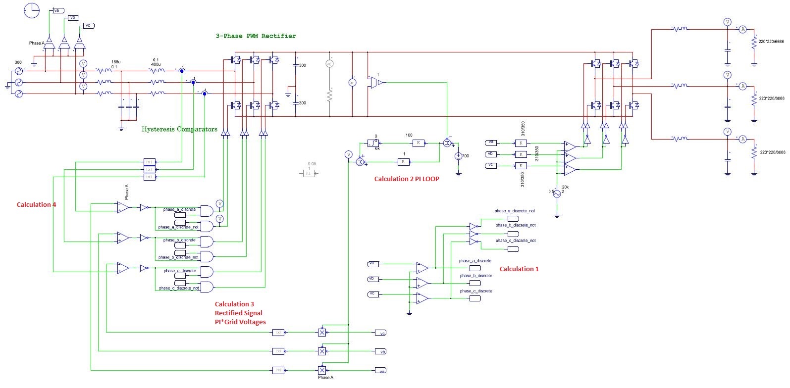
I'm working on 3 phase rectifier project. And I am tring different control loops. My last control loop scheme has been added as a picture. But i have some questions.

Calculation 1 -> I get the phasse angle the grid.

Calculation 2 -> This is PI loop for DC capacitor.

Calculation 3 -> Here , I rectify the signal which is multiplication of PI loop output and grid voltages.

Calculation 4 -> I compare measured and rectified Current and result of calculation 3 after that i get the value of comparison which are 0 and 1. Than i apply the result of calculation 4 to IGBT by using the result of  calculation 1 for apply the correct transistor.

I have explained my control loop briefly above.Simulation results are good. But I encountered some challenges when applying control loop in microontroller.

Question 1 -> My calculation 4 results are binary already. How could I drive IGBT in the right cycle of grid by using PWM module ? Because it seems easier to set up GPIO. How should i set up PWM module ?

Question 2 -> Control loop results are satisfying. But is it appropriate in practice ? Is there any other method you can recommend ? Especially for current loop ?
Question 3 -> My control loop is 20 khz and I am reading all ADC in this frequency than i calculate all operations about control loop in this duration. Is it too fast ? Should I read and calculate the PI and DC Capasitor  in 10 Hz. Would it be benefitial for results ?

  • Wltr0,

    This is 20 questions bundled into one forum post :D, you will not be satisfied by whatever I might reply :) as the questions themselves are more consulting in nature, where you pay someone to consult you on the implementation.

    1. For hysteresis control, we don't have a good example that i can point to that we have done. There is a lot more to it than what meets the eye here, what are the limits on the switching frequency on your hysteresis controller etc. I believe you have asked this question previously.

    2. We currently don;t have any hysteresis based current controller design, nor a three phase PFC (we do have vienn rectifier TIDM-1000) but not the one you are looking at right now. Hence i cannot recommend anything on this.

    2. F28069 should have enough performance to do what you are doing from a bandwidth perspective.

    Maybe some one from the community can help, but from TI side I am not sure how i can provide you a specific answer for such a broad question.

    regards
    Manish

  • Thank you for your answer Manish , you are right.

    Okay then, I ask specific question.

    I have a result which is compare value 1 and 0. And I want to output this signal without changing  by using PWM module. Do you have suggestions ?

    For 3. question I have two options. First option I read DC Capacitor 10 Khz and calculate all control loop in 20 Khz. Second option I read DC Capacitor 10 Hz and calculate all control loop in 20 Khz . Which makes more sense ? 

    Thank you again.

  • 1. I have a result which is compare value 1 and 0. And I want to output this signal without changing by using PWM module. Do you have suggestions ?

    Once you have compare even, the compare event can be used by the PWM module. They go directly to the DCAEVT block in the PWM and the PWM can be configured to trip/ change states accordingly. Considering you are on F28069, there are not many system examples i can point to you, but you can look at the following example and study the code

    C:\Git\digital_power_sdk\c2000ware\device_support\f2806x\examples\c28\epwm_dcevent_trip
    C:\Git\digital_power_sdk\c2000ware\device_support\f2806x\examples\c28\epwm_dcevent_trip_comp

    2. Most of the times we do a fast and a slow ISR, bt typically all control values are read in the fast ISR which in your case will be 20kHz. I will not be too worried about them fitting on F28069 and if i were you i will read everything in fast 20kHz ISR. If you are too worried you can also do that in 10kHz ISR. 10Hz will be too slow. Also, remember you have the CLA on F28069 and you can effectively double the CPU bandwidth when you use CLA.