This thread has been locked.

If you have a related question, please click the "Ask a related question" button in the top right corner. The newly created question will be automatically linked to this question.

28335: Connecting 2 SPI devices to the SPI input

Hi,

I have 2 separate SPI devices:

The first is a variable resistor controlled by SPI.

The second is a variable oscillator controlled by SPI.

How can I connect both of them to the SPI-A on the 28335 ? How ?

I can not use MCBSP. Is it used for external A2D.

Thanks.

  • There are 2 McBSP modules on the 28335 - are you using both for your external A2D?

    I've also heard of some people simulating a SPI via a bit-banging method (you may be able to Google search this option).

    Do the variable resistor and variable oscillator need the SPI module both at the same time?  If yes, one of the above methods should be used.

    If not, you might try connecting the variable resistor to one set of GPIO pins for SPI-A (GPIO16, 17, 18, 19), and then connect the  variable oscillator to a different set of GPIO pins for SPI-A (GPIO 54, 55, 56, 57).

    When you want to communicate with the variable oscillator:

    1. Configure SPI-A for use with the variable oscillator.
    2. switch the GPIO mux over to the variable oscillator SPI pins (16, 17, 18, 19)
    3. Run code for variable oscillator

    When you want to communicate with the variable resistor:

    1. Disable the variable resistor SPI-A GPIO pins (16, 17, 18, 19) - in other words, switch back to GPIO pins with INPUT direction, Pull-ups enabled.
    2. flush out the SPI tx/rx buffers, disable, reset SPI
    3. Configure SPI-A for use with the variable resistor.
    4. switch the GPIO mux over to the variable resistor pins (54, 55, 56, 57)
    5. Run code for variable oscillator.


    DISCLAIMER: I have not tried the above myself, but in theory it seems that it would work - but only if you are not using the variable resistor and variable oscillator at the same time. You might need to test/tweak the software here and there to see how it works for you...

  • Hi,

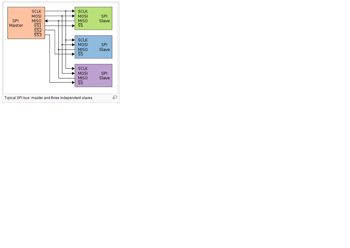
     Please look at the following image taken from: http://en.wikipedia.org/wiki/Serial_Peripheral_Interface_Bus

    Is it possible using this method in the 28335 ?

    Thanks.


  • Yes,

    You could potentially do this, but disable the SPISTEA pin (use as regular GPIO pin) and manually control normal GPIO pins for your SS line for the different slave devices. (since there is only 1 SPISTE signal for SPI-A).

  • Can we use general purpose I/O rather than SPISTEx to enable the slave?

  • Yes we can you use GPIO as an  SPISTEx to enable the slave.