This thread has been locked.

If you have a related question, please click the "Ask a related question" button in the top right corner. The newly created question will be automatically linked to this question.

CCS/TMS320F28035: TMS320F28035 3-wire SPI configuration issue

Part Number: TMS320F28035


Tool/software: Code Composer Studio

Hi,
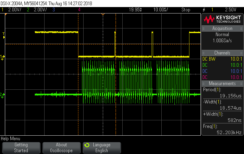
       I'm using the TMS320F28035's SPI, to get an angle sensor's angle data. The SPI is configured in 3-wire master mode. To read the sensor's data, first configure the SPI to transmit mode, send the sensor's address and command data (16 bytes), then configure the SPI to receive mode, read the sensor's angle data (16 bytes), and then read the checksum status data (16 bytes). During the whole process, the chip select signal(CSN) should be pulled low all the time, but by measuring, the chip select signal, each time the 16-byte transfer is completed, it will be pulled up once. This will not meet the timing requirements of the sensor. How do I configure the SPI so that the chip select signal stays low for the entire period.
This is part of my program and the screenshot of oscilloscope ,the yellow line is chip select signal,the green line is clock signal.
Thanks!

  • This is the expected behavior of the SPI. Once there is no data available in the SPI transmit buffers, the SPISTE will be driven inactive.

    You will want to control the Chip select signal manually. just configure it to GPIO mode and drive it before and after your complete transfer. You can check out a few threads of for similar topics. They refer to multiple slaves, but the technique is the same.
    e2e.ti.com/.../613315
    e2e.ti.com/.../591822

    Basically just drop in a GPIO_set_low function after your //See demo line, and then GPIO_set_high after your last SW = readSPI .

    Regards,
    Mark