This thread has been locked.

If you have a related question, please click the "Ask a related question" button in the top right corner. The newly created question will be automatically linked to this question.

TMS320F280049: HWPWM phase offset between PWM1 and PWM2 is changing..

Part Number: TMS320F280049
Other Parts Discussed in Thread: C2000WARE

Hello Experts,

I am testing below sample code.

C:\ti\c2000\C2000Ware_1_00_05_00\device_support\f2837xd\examples\cpu1\hrpwm_deadband_sfo_v8\cpu01\hrpwm_deadband_sfo_v8.c

Since this is the code for F2837x, I modified below function for F280049. 

InitEPwm1Gpio();
InitEPwm2Gpio();

Now below are pictures for PWM1A and PWM2A. In conjunction with period sweep, the phase between PWM1 and PWM2 are changing.

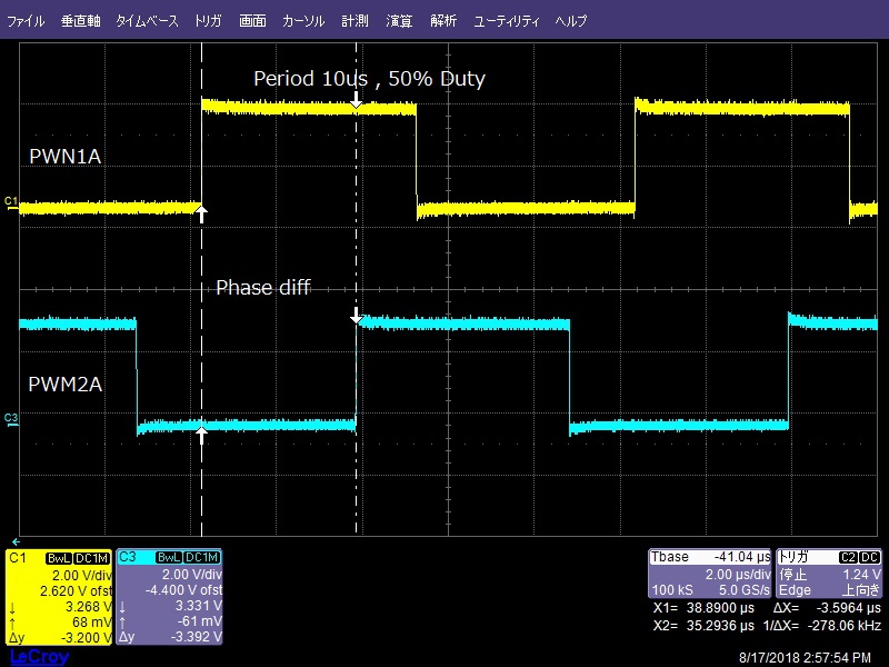
It looks like that the source code sets the updated phase is always a half of the new period but does not look like it. If setting InputPeriodInc parameter to zero, the phase is fixed. I'd like to fix the phase like 120 degree even when the period is changed.

Is this behavior expected? Or do I miss something?

Regards,

Uchikoshi

  • Hi,
    You can set the phase to 120 degree. Example is only to show case the simultaneous of change of period and frequency, using InputPeriodInc parameter.
    Are you observing any different when you set the phase to 120 degree - it doesn't have to be 50% as shown in example.

  • Hello

    I tested on F28075 which originally supports below sample code.

    C:\ti\c2000\C2000Ware_1_00_05_00\device_support\f2807x\examples\cpu1\hrpwm_deadband_sfo_v8\cpu01\hrpwm_deadband_sfo_v8.c

    It looks fine that the phase between PWM1 and PWM2 are fixed though there is a little jittter.

    For my case, I  ported hrpwm_deadband_sfo_v8.c into F28004x as attached. In this case , the phase between PWM1 and PWM2 is not fixed. Could you please confirm if you can see the same behavior what I saw?

    //###########################################################################
    //
    // FILE:    hrpwm_deadband_sfo_v8.c
    //
    // TITLE:   F2837xD Device HRPWM SFO V8 High-Resolution Dead-Band
    //          (up-down count) example
    //
    //! \addtogroup cpu01_example_list
    //! <h1> HRPWM Dead-Band Example (hrpwm_deadband_sfo_v8)</h1>
    //! This program requires the F2837xD header files, including the
    //! following files required for this example:
    //! SFO_V8.h and SFO_v8_fpu_lib_build_c28.lib
    //!
    //! Monitor ePWM1 & ePWM2 A/B pins on an oscilloscope
    //!
    //! DESCRIPTION:
    //!
    //! This example sweeps the ePWM frequency while maintaining a duty cycle of
    //! ~50% in ePWM up-down count mode. In addition, this example demonstrates
    //! ePWM high-resolution dead-band (HRDB) capabilities utilizing the HRPWM
    //! extension of the respective ePWM module.
    //!
    //! This example calls the following TI's micro-edge positioner (MEP) Scale
    //! Factor Optimizer (SFO) software library V8 functions:
    //!
    //! \b int \b SFO(); \n
    //! updates MEP_ScaleFactor dynamically when HRPWM is in use
    //! updates HRMSTEP register (exists only in EPwm1Regs register space)
    //! which updates MEP_ScaleFactor value
    //! - returns 0 if not complete for the specified channel
    //! - returns 1 when complete for the specified channel
    //! - returns 2 if error: MEP_ScaleFactor is greater than maximum value of 255
    //! (Auto-conversion may not function properly under this condition)
    //!
    //! This example is intended to demonstrate the HRPWM capability to control
    //! the dead-band falling edge delay (FED) and rising edge delay (RED).
    //!
    //! ePWM1 and ePWM2 A/B channels will have fine edge movement due to HRPWM
    //! control.
    //!
    //!=======================================================================
    //! NOTE: For more information on using the SFO software library, see the
    //! F2837xD High-Resolution Pulse Width Modulator (HRPWM) Chapter in the
    //! Technical Reference Manual.
    //!=======================================================================
    //!
    //! To load and run this example:
    //! -# **!!IMPORTANT!!** - in SFO_V8.h, set PWM_CH to the max number of
    //!    HRPWM channels plus one. For example, for the F2837xD, the
    //!    maximum number of HRPWM channels is 8. 8+1=9, so set
    //!    #define PWM_CH 9 in SFO_V8.h. (Default is 8)
    //! -# Run this example at maximum SYSCLKOUT
    //! -# Activate Real time mode
    //! -# Run the "AddWatchWindowVars_HRPWM.js" script from the scripting console
    //!    (View -> Scripting Console) to populate watch window by using the
    //!    command:
    //!    loadJSFile <path_to_JS_file>/AddWatchWindowVars_HRPWM.js
    //! -# Run the code
    //! -# Watch ePWM A / B channel waveforms on an oscilloscope
    //! -# In the watch window:
    //!    Change the variable InputPeriodInc to increase or decrease the frequency
    //!    sweep rate. Setting InputPeriodInc = 0 will stop the sweep while
    //!    allowing other variables to be manipulated and updated in real time.
    //! -# In the watch window:
    //!    Change values for registers EPwm1Regs.DBRED/EPwm2Regs.DBRED to see
    //!    changes in rising edge dead-bands for ePWM1 and ePWM2 respectively.
    //!    Alternatively, changing values for registers
    //!    EPwm1Regs.DBFED/EPwm2Regs.DBFED will change falling edge dead-bands for
    //!    ePWM1 and ePWM2. Changing these values will alter the duty cycle
    //!    percentage for their respective ePWM modules.
    //!    **!!NOTE!!** - DBRED/DBFED values should never be set below 4.
    //!                   Do not set these values to 0, 1, 2 or 3.
    //! -# In the watch window:
    //!    Change values for registers
    //!    EPwm1Regs.DBREDHR.bit.DBREDHR/EPwm2Regs.DBREDHR.bit.DBREDHR to increase
    //!    or decrease number of resolvable high-resolution steps at the
    //!    dead-band rising edge. Alternatively, change values for
    //!    EPwm1Regs.DBFEDHR.bit.DBFEDHR/EPwm2Regs.DBFEDHR.bit.DBFEDHR to change
    //!    the number of resolvable steps at the dead-band falling edge for ePWM1
    //!    and ePWM2 respectively.
    //
    //###########################################################################
    // $TI Release: F2837xD Support Library v3.05.00.00 $
    // $Release Date: Tue Jun 26 03:15:23 CDT 2018 $
    // $Copyright:
    // Copyright (C) 2013-2018 Texas Instruments Incorporated - http://www.ti.com/
    //
    // Redistribution and use in source and binary forms, with or without 
    // modification, are permitted provided that the following conditions 
    // are met:
    // 
    //   Redistributions of source code must retain the above copyright 
    //   notice, this list of conditions and the following disclaimer.
    // 
    //   Redistributions in binary form must reproduce the above copyright
    //   notice, this list of conditions and the following disclaimer in the 
    //   documentation and/or other materials provided with the   
    //   distribution.
    // 
    //   Neither the name of Texas Instruments Incorporated nor the names of
    //   its contributors may be used to endorse or promote products derived
    //   from this software without specific prior written permission.
    // 
    // THIS SOFTWARE IS PROVIDED BY THE COPYRIGHT HOLDERS AND CONTRIBUTORS 
    // "AS IS" AND ANY EXPRESS OR IMPLIED WARRANTIES, INCLUDING, BUT NOT 
    // LIMITED TO, THE IMPLIED WARRANTIES OF MERCHANTABILITY AND FITNESS FOR
    // A PARTICULAR PURPOSE ARE DISCLAIMED. IN NO EVENT SHALL THE COPYRIGHT 
    // OWNER OR CONTRIBUTORS BE LIABLE FOR ANY DIRECT, INDIRECT, INCIDENTAL, 
    // SPECIAL, EXEMPLARY, OR CONSEQUENTIAL DAMAGES (INCLUDING, BUT NOT 
    // LIMITED TO, PROCUREMENT OF SUBSTITUTE GOODS OR SERVICES; LOSS OF USE,
    // DATA, OR PROFITS; OR BUSINESS INTERRUPTION) HOWEVER CAUSED AND ON ANY
    // THEORY OF LIABILITY, WHETHER IN CONTRACT, STRICT LIABILITY, OR TORT 
    // (INCLUDING NEGLIGENCE OR OTHERWISE) ARISING IN ANY WAY OUT OF THE USE 
    // OF THIS SOFTWARE, EVEN IF ADVISED OF THE POSSIBILITY OF SUCH DAMAGE.
    // $
    //###########################################################################
    
    //
    // Included Files
    //
    #include "F28x_Project.h"
    #include "SFO_V8.h"
    
    //
    // Defines
    //
    #define PWM_CH              9   // # of PWM channels + 1
    #define HR_ENABLED          1   // 1 = HR behavior
                                    // 0 = non-HR behavior
    
    #define PERIOD_MAX 600
    #define PERIOD_MIN 360
    
    
    #define DEVICE_GPIO_PIN_LED1    31
    
    #define TOGLLE {        static Uint16 pinStatus = 0; \
            do { \
                if (pinStatus == 0) { \
                    GPIO_WritePin(DEVICE_GPIO_PIN_LED1, 1); \
                    pinStatus = 1;   \
                    break;  \
                }            else            {  \
                    GPIO_WritePin(DEVICE_GPIO_PIN_LED1, 0);  \
                    pinStatus = 0; \
                    break;             }        }while(1);}


    //
    // Globals
    //
    Uint16 UpdateFine, status;
    Uint16 temp_REM2 = 0, temp_PHS2, PhaseFine2;
    
    Uint32 CountUpdatefine = 0, CountUpdateMax = 0;
    Uint16 Period = 0, PeriodFine = 0, PeriodOdd = 0;
    Uint16 PeriodIncrement = 0, PeriodFineIncrement = 0;
    Uint32 InputPeriodInc = 0;
    Uint32 PeriodFine_temp = 0;
    Uint16 PWM1 = 1;
    Uint16 PWM2 = 2;
    //$$$ Uint16 PeriodMax = 600, PeriodMin = 360; $$$ #Define�ɕύX
    
    //
    // Array of pointers to EPwm register structures:
    // *ePWM[0] is defined as dummy value not used in the example
    //
    volatile struct EPWM_REGS *ePWM[PWM_CH] =
                 {  &EPwm1Regs, &EPwm1Regs, &EPwm2Regs, &EPwm3Regs, &EPwm4Regs,
                    &EPwm5Regs, &EPwm6Regs, &EPwm7Regs, &EPwm8Regs};
    int MEP_ScaleFactor;
    
    //
    // Function Prototypes
    //
    void HRPWM1_Config(int);
    void HRPWM2_Config(int);
    void FreqCtl_func(void);
    void initHRPWM1GPIO(void);
    void initHRPWM2GPIO(void);
    interrupt void PRDEQfix_ISR(void);
    void error(void);
    
    //
    // Main
    //
    void main(void)
    {
        //
        // Initialize System Control for Control and Analog Subsystems.
        // Enable Peripheral Clocks.
        // This example function is found in the F2837xD_SysCtrl.c file.
        //
        InitSysCtrl();
    
        EALLOW;
        ClkCfgRegs.SYSCLKDIVSEL.bit.PLLSYSCLKDIV = 1;
        EDIS;
    
        //
        // Disable CPU interrupts
        //
        DINT;
    
    
        InitGpio();
        GPIO_SetupPinMux(DEVICE_GPIO_PIN_LED1, GPIO_MUX_CPU1, 0);
        GPIO_SetupPinOptions(DEVICE_GPIO_PIN_LED1, GPIO_OUTPUT, GPIO_PUSHPULL);


        //
        // Initialize the PIE control registers to their default state.
        // The default state is all PIE interrupts disabled and flags
        // are cleared.
        // This function is found in the F2837xD_PieCtrl.c file.
        //
        InitPieCtrl();
    
        //
        // Disable CPU interrupts and clear all CPU interrupt flags
        //
        IER = 0x0000;
        IFR = 0x0000;
    
        //
        // Initialize the PIE vector table with pointers to the shell Interrupt
        // Service Routines (ISR).
        // This will populate the entire table, even if the interrupt
        // is not used in this example. This is useful for debug purposes.
        // The shell ISR routines are found in F2837xD_DefaultIsr.c.
        // This function is found in F2837xD_PieVect.c.
        //
        InitPieVectTable();
    
        //
        // Set address of ISR in PIE vector table
        //
        EALLOW;
        PieVectTable.EPWM1_INT = &PRDEQfix_ISR;
        EDIS;
    
        //
        // Calling SFO() updates the HRMSTEP register with calibrated
        // MEP_ScaleFactor. HRMSTEP must be populated with a scale factor value
        // prior to enabling high resolution period control.
        //
        status = SFO_INCOMPLETE;
        while(status == SFO_INCOMPLETE)
        {
            //
            // Call until complete
            //
            status = SFO();
            if (status == SFO_ERROR)
            {
                error();
            }
        }
    
        EALLOW;
        CpuSysRegs.PCLKCR0.bit.TBCLKSYNC = 0;
        EDIS;
    
        //
        // Init HRPWM1/HRPWM2
        //
        initHRPWM1GPIO();
        initHRPWM2GPIO();
        HRPWM1_Config(PERIOD_MIN);
        HRPWM2_Config(PERIOD_MIN);
    
        EALLOW;
        CpuSysRegs.PCLKCR0.bit.TBCLKSYNC = 1;   // Resync PWM timebase clock
        (*ePWM[PWM1]).GLDCTL2.bit.OSHTLD = 1;  // This should also write to
                                                // GLDCTL2 of PWM2
        EDIS;
    
        //
        // Configure ePWM1 to generate interrupts on period match
        //
        (*ePWM[PWM1]).ETSEL.bit.INTSEL = 1;   // Interrupt on counter zero match
        (*ePWM[PWM1]).ETSEL.bit.INTEN = 1;     // Enable peripheral interrupt
        (*ePWM[PWM1]).ETPS.bit.INTPRD = 1;     // Generate interrupt on every event
        PieCtrlRegs.PIEIER3.bit.INTx1 = 1;     // Enable ePWM1 interrupt in PIE
    
        IER |= 0x0004;                         // Enable core INT #3
        EINT;                                  // Clear global interrupt mask
    
        UpdateFine = 0;                        // Disable continuous updates
        Period = PERIOD_MIN;
        PeriodFine = 0x0;
        CountUpdateMax = 0x0FFFF;
        CountUpdatefine = CountUpdateMax;
    
        //
        // Watch window variable to modify the rate of the frequency sweep
        //
        InputPeriodInc = 6554 ;// 0; // 6553;
    
        for(;;)
        {
            while(UpdateFine == 0)
            {
                if(CountUpdatefine >= CountUpdateMax)
                {
                    if(Period < PERIOD_MAX)
                    {
                        //
                        // Perform sweep
                        //
                        PeriodIncrement = InputPeriodInc >> 16;  //$$$ ��16�r�b�g�V�t�g����ƌ���������̂ňӖ��Ȃ��H
                        PeriodFineIncrement = (Uint16)InputPeriodInc;
                        Period = Period + PeriodIncrement;
                        PeriodFine_temp = (Uint32)PeriodFine +
                                                     (Uint32)PeriodFineIncrement;
                        if(PeriodFine_temp >= 0x10000)
                        {
                            PeriodFine_temp = PeriodFine_temp - 0x10000;
                            Period = Period + 1;
                        }
    
                        //
                        // Period is odd - CMP is divide by 2 for 50% duty
                        //
                        if (Period % 2 == 1)
                        {
                            PeriodOdd = 1;
                        }
                        else
                        {
                            PeriodOdd = 0;
                        }
    
                        PeriodFine = (Uint16) PeriodFine_temp;
    
                        //
                        // Update PWM values for non-zero increment
                        //
                        if (InputPeriodInc != 0)
                        {
                            FreqCtl_func();
                        }
                    }
                    else
                    {
                        Period = PERIOD_MIN;
                        PeriodFine = 0;
                        if (InputPeriodInc != 0)
                        {
                            FreqCtl_func();
                        }
                    }
                    CountUpdatefine = 0;
    
                    TOGLLE;
    
                }
                CountUpdatefine++;
            }
        }
    }
    
    //
    // HRPWM1_Config - ePWM1 register configuration with HRPWM
    //                 ePWM1A toggle low/high with MEP control on Rising edge
    //
    void HRPWM1_Config(PeriodConfig)
    {
        (*ePWM[PWM1]).TBCTL.bit.PRDLD = TB_SHADOW;  // Set Immediate load
    
        //
        // PWM frequency = 1 / PeriodConfig
        //
        (*ePWM[PWM1]).TBPRD = PeriodConfig;
    
        //
        // Set duty 50% initially and initialize HRPWM extension
        //
        (*ePWM[PWM1]).CMPA.bit.CMPA = PeriodConfig / 2;
        (*ePWM[PWM1]).CMPA.bit.CMPAHR = (1 << 8);
        (*ePWM[PWM1]).CMPB.bit.CMPB = PeriodConfig / 2;
        (*ePWM[PWM1]).CMPB.bit.CMPBHR = (1 << 8);
        (*ePWM[PWM1]).TBPHS.all = 0;
        (*ePWM[PWM1]).TBCTR = 0;
    
        (*ePWM[PWM1]).TBCTL.bit.CTRMODE = TB_COUNT_UPDOWN;
        (*ePWM[PWM1]).TBCTL.bit.PHSEN = TB_DISABLE;   // ePWM1 is the Master
        (*ePWM[PWM1]).TBCTL.bit.SYNCOSEL = TB_SYNC_IN;
        (*ePWM[PWM1]).TBCTL.bit.HSPCLKDIV = TB_DIV1;
        (*ePWM[PWM1]).TBCTL.bit.CLKDIV = TB_DIV1;
    
        //
        // LOAD CMPA on CTR = ZERO_PRD
        //
        (*ePWM[PWM1]).CMPCTL.bit.LOADAMODE = CC_CTR_ZERO_PRD;
        (*ePWM[PWM1]).CMPCTL.bit.LOADBMODE = CC_CTR_ZERO_PRD;
    
        (*ePWM[PWM1]).CMPCTL.bit.SHDWAMODE = CC_SHADOW;
        (*ePWM[PWM1]).CMPCTL.bit.SHDWBMODE = CC_SHADOW;
    
        (*ePWM[PWM1]).AQCTLA.bit.CAU = AQ_SET;
        (*ePWM[PWM1]).AQCTLA.bit.CAD = AQ_CLEAR;
    
        EALLOW;
    #if HR_ENABLED
        (*ePWM[PWM1]).HRCNFG.all = 0x1353;
    
        //
        // Turn on high-resolution period control
        //
        (*ePWM[PWM1]).HRPCTL.bit.HRPE = 1;
    
        //
        // Synchronize high resolution phase to start HR period
        //
        (*ePWM[PWM1]).TBCTL.bit.SWFSYNC = 1;
    #endif
    
        (*ePWM[PWM1]).GLDCFG.bit.CMPA_CMPAHR = 1;
        (*ePWM[PWM1]).GLDCFG.bit.CMPB_CMPBHR = 1;
    
        //
        // Load on CTR = ZERO_PRD (2) / ZERO (1)
        //
        (*ePWM[PWM1]).GLDCTL.bit.GLDMODE = 2;
    
        //
        // One shot mode and global load enabled
        //
        (*ePWM[PWM1]).GLDCTL.bit.OSHTMODE = 1;
        (*ePWM[PWM1]).GLDCTL.bit.GLD = 1;
    
        //
        // Write to PWM1 GLDCTL2 will result in simultaneous write to PWM2 GLDCTL2
        //
        (*ePWM[PWM1]).EPWMXLINK.bit.GLDCTL2LINK = PWM1 - 1;
        (*ePWM[PWM1]).DBCTL.bit.OUT_MODE = DB_FULL_ENABLE;
        (*ePWM[PWM1]).DBCTL.bit.POLSEL = DB_ACTV_HIC;
        (*ePWM[PWM1]).DBCTL.bit.IN_MODE = DBA_ALL;
        (*ePWM[PWM1]).DBCTL.bit.SHDWDBREDMODE = 1;
        (*ePWM[PWM1]).DBCTL.bit.SHDWDBFEDMODE = 1;
        (*ePWM[PWM1]).DBCTL.bit.LOADREDMODE = 0;    // Load on Counter == 0
        (*ePWM[PWM1]).DBCTL.bit.LOADFEDMODE = 0;    // Load on Counter == 0
        (*ePWM[PWM1]).DBCTL.bit.HALFCYCLE = 1;
        (*ePWM[PWM1]).DBRED.bit.DBRED = 4;
        (*ePWM[PWM1]).DBREDHR.bit.DBREDHR = 0x0;
        (*ePWM[PWM1]).DBFED.bit.DBFED = 4;
        (*ePWM[PWM1]).DBFEDHR.bit.DBFEDHR = 0x0;
    
        (*ePWM[PWM1]).HRCNFG2.bit.EDGMODEDB = HR_BEP;    // DBREDHR and DBFEDHR
        (*ePWM[PWM1]).HRCNFG2.bit.CTLMODEDBRED = 0; // Load on ZRO
        (*ePWM[PWM1]).HRCNFG2.bit.CTLMODEDBFED = 0; // Load on ZRO
        (*ePWM[PWM1]).DBREDHR.bit.DBREDHR = (0 << 9);
    
        EDIS;
    }
    
    //
    // HRPWM2_Config - ePWM2 register configuration with HRPWM
    //                 ePWM2A toggle low/high with MEP control on Rising edge
    //
    void HRPWM2_Config(PeriodConfig)
    {
        (*ePWM[PWM2]).TBCTL.bit.PRDLD = TB_SHADOW;  // Set Immediate load
    
        //
        // PWM frequency = 1 / PeriodConfig
        //
        (*ePWM[PWM2]).TBPRD = PeriodConfig;
    
        //
        // Set duty 50% initially and initialize HRPWM extension
        //
        (*ePWM[PWM2]).CMPA.bit.CMPA = PeriodConfig / 2;
        (*ePWM[PWM2]).CMPA.bit.CMPAHR = (1 << 8);
        (*ePWM[PWM2]).CMPB.bit.CMPB = PeriodConfig / 2;
        (*ePWM[PWM2]).CMPB.bit.CMPBHR = (1 << 8);
        (*ePWM[PWM2]).TBPHS.all = 0;
        (*ePWM[PWM2]).TBCTR = 0;
    
        (*ePWM[PWM2]).TBCTL.bit.CTRMODE = TB_COUNT_UPDOWN;
        (*ePWM[PWM2]).TBCTL.bit.PHSEN = TB_DISABLE;   // ePWM1 is the Master
    //    (*ePWM[PWM2]).TBCTL.bit.PHSEN = TB_ENABLE;   // ePWM1 is the Master
        (*ePWM[PWM2]).TBCTL.bit.SYNCOSEL = TB_SYNC_IN;
        (*ePWM[PWM2]).TBCTL.bit.HSPCLKDIV = TB_DIV1;
        (*ePWM[PWM2]).TBCTL.bit.CLKDIV = TB_DIV1;
    
        //
        // LOAD CMPA on CTR = 0
        //
        (*ePWM[PWM2]).CMPCTL.bit.LOADAMODE = CC_CTR_ZERO_PRD;
        (*ePWM[PWM2]).CMPCTL.bit.LOADBMODE = CC_CTR_ZERO_PRD;
        (*ePWM[PWM2]).CMPCTL.bit.SHDWAMODE = CC_SHADOW;
        (*ePWM[PWM2]).CMPCTL.bit.SHDWBMODE = CC_SHADOW;
    
        (*ePWM[PWM2]).AQCTLA.bit.CAU = AQ_SET;
        (*ePWM[PWM2]).AQCTLA.bit.CAD = AQ_CLEAR;
    
        EALLOW;
    #if HR_ENABLED
        (*ePWM[PWM2]).HRCNFG.all = 0x1353;
    
        //
        // Turn on high-resolution period control
        //
        (*ePWM[PWM2]).HRPCTL.bit.HRPE = 1;
    
        //
        // Synchronize high resolution phase to start HR period
        //
        (*ePWM[PWM2]).TBCTL.bit.SWFSYNC = 1;
    #endif
    
        (*ePWM[PWM2]).TBCTL.bit.PHSDIR = 1;        // Count up after SYNC event
        (*ePWM[PWM2]).TBPHS.bit.TBPHS = 180;
    
        (*ePWM[PWM2]).GLDCFG.bit.CMPA_CMPAHR = 1;
        (*ePWM[PWM2]).GLDCFG.bit.CMPB_CMPBHR = 1;
    
        //
        // Load on CTR = ZERO_PRD (2) / ZERO (1)
        //
        (*ePWM[PWM2]).GLDCTL.bit.GLDMODE = 2;
    
        //
        // One shot mode and global load enabled
        //
        (*ePWM[PWM2]).GLDCTL.bit.OSHTMODE = 1;
        (*ePWM[PWM2]).GLDCTL.bit.GLD = 1;
    
        //
        // Write to PWM1 GLDCTL2 will result in simultaneous write to PWM2 GLDCTL2
        //
        (*ePWM[PWM2]).EPWMXLINK.bit.GLDCTL2LINK = PWM1 - 1;
        (*ePWM[PWM2]).DBCTL.bit.OUT_MODE = DB_FULL_ENABLE;
        (*ePWM[PWM2]).DBCTL.bit.POLSEL = DB_ACTV_HIC;
        (*ePWM[PWM2]).DBCTL.bit.IN_MODE = DBA_ALL;
        (*ePWM[PWM2]).DBCTL.bit.SHDWDBREDMODE = 1;
        (*ePWM[PWM2]).DBCTL.bit.SHDWDBFEDMODE = 1;
        (*ePWM[PWM2]).DBCTL.bit.LOADREDMODE = 0;    // Load on Counter == 0
        (*ePWM[PWM2]).DBCTL.bit.LOADFEDMODE = 0;    // Load on Counter == 0
        (*ePWM[PWM2]).DBCTL.bit.HALFCYCLE = 1;
        (*ePWM[PWM2]).DBRED.bit.DBRED = 4;
        (*ePWM[PWM2]).DBREDHR.bit.DBREDHR = 0x0;
        (*ePWM[PWM2]).DBFED.bit.DBFED = 4;
        (*ePWM[PWM2]).DBFEDHR.bit.DBFEDHR = 0x0;
    
        (*ePWM[PWM2]).HRCNFG2.bit.EDGMODEDB = HR_BEP;    // DBREDHR and DBFEDHR
        (*ePWM[PWM2]).HRCNFG2.bit.CTLMODEDBRED = 0; // Load on ZRO
        (*ePWM[PWM2]).HRCNFG2.bit.CTLMODEDBFED = 0; // Load on ZRO
        (*ePWM[PWM2]).DBREDHR.bit.DBREDHR = (0 << 9);
    
        EDIS;
    }
    
    //
    // FreqCtl_func - Frequency modulation & phase sync function
    // This function is called only if frequency sweep is enabled
    //
    void FreqCtl_func(void)
    {
        if (PeriodOdd)
        {
            //
            // Add 0.5 if period is odd
            //
            (*ePWM[PWM1]).CMPA.bit.CMPAHR = (PeriodFine >> 1) + 0x7FFF;
            (*ePWM[PWM2]).CMPA.bit.CMPAHR = (PeriodFine >> 1) + 0x7FFF;
            (*ePWM[PWM1]).CMPB.bit.CMPBHR = (PeriodFine >> 1) + 0x7FFF;
            (*ePWM[PWM2]).CMPB.bit.CMPBHR = (PeriodFine >> 1) + 0x7FFF;
        }
        else
        {
            (*ePWM[PWM1]).CMPA.bit.CMPAHR = PeriodFine >> 1;
            (*ePWM[PWM2]).CMPA.bit.CMPAHR = PeriodFine >> 1;
            (*ePWM[PWM1]).CMPB.bit.CMPBHR = PeriodFine >> 1;
            (*ePWM[PWM2]).CMPB.bit.CMPBHR = PeriodFine >> 1;
        }
    
        (*ePWM[PWM1]).CMPA.bit.CMPA = (Period >> 1) + 1;
        (*ePWM[PWM2]).CMPA.bit.CMPA = (Period >> 1) + 1;
        (*ePWM[PWM1]).CMPB.bit.CMPB = (Period >> 1) + 1;
        (*ePWM[PWM2]).CMPB.bit.CMPB = (Period >> 1) + 1;
    
        temp_PHS2 = (Period >> 1);
    
        switch(PeriodOdd)
        {
            case 1:
                //
                // Accounting for divide by 2 = 0.5
                //
                PhaseFine2 =  0xFF - (PeriodFine >> 9) - 0x7F;
                break;
    
            default:
                PhaseFine2 =  0xFF - (PeriodFine >> 9);
                break;
        }
    
        //
        // No fractional phase shift to account for
        //
        temp_REM2 =  (Uint16) 0x100 + PhaseFine2;
        UpdateFine = 1;
    
    }
    
    //
    // PRDEQfix_ISR - ISR for Translator remainder calculations
    //
    interrupt void PRDEQfix_ISR(void)
    {
        EALLOW;


        if (UpdateFine == 1)
        {
            //
            // This should also write to GLDCTL2 of PWM2, PWM3 and PWM4
            //
            (*ePWM[PWM1]).GLDCTL2.bit.OSHTLD = 1;
    
            //
            // TBCTR phase load on SYNC (required for updown count HR control
            //
            (*ePWM[PWM2]).TBCTL.bit.PHSEN = TB_ENABLE;
    
            //
            // Coarse phase offset relative to ePWM1
            //
            (*ePWM[PWM2]).TBPHS.bit.TBPHS = temp_PHS2;
            (*ePWM[PWM2]).TRREM.bit.TRREM = temp_REM2;
    
            (*ePWM[PWM2]).TBPRDHR = PeriodFine;
            (*ePWM[PWM2]).TBPRD = Period;
    
            (*ePWM[PWM1]).TBPRDHR = PeriodFine;
            (*ePWM[PWM1]).TBPRD = Period;
            (*ePWM[PWM1]).TRREM.bit.TRREM = 0x100;
            UpdateFine = 0;
        }
        else
        {
            (*ePWM[PWM2]).TBCTL.bit.PHSEN = TB_DISABLE;
        }
    
        //
        // Re-initialize for next PWM interrupt
        //
        PieCtrlRegs.PIEACK.all = PIEACK_GROUP3;     // Acknowledge PIE interrupt
        (*ePWM[PWM1]).ETCLR.bit.INT = 1;            // Clear interrupt bit
        EDIS;
    }


    //
    // initHRPWM1GPIO - Initialize HRPWM1 GPIOs
    //
    void initHRPWM1GPIO(void)
    {
        EALLOW;
    
        //
        // Disable internal pull-up for the selected output pins
        // for reduced power consumption
        // Pull-ups can be enabled or disabled by the user.
        //
        GpioCtrlRegs.GPAPUD.bit.GPIO0 = 1;    // Disable pull-up on GPIO0 (EPWM1A)
        GpioCtrlRegs.GPAPUD.bit.GPIO1 = 1;    // Disable pull-up on GPIO1 (EPWM1B)
    
        //
        // Configure EPWM-1 pins using GPIO regs
        // This specifies which of the possible GPIO pins will be EPWM1 functional
        // pins.
        //
        GpioCtrlRegs.GPAMUX1.bit.GPIO0 = 1;   // Configure GPIO0 as EPWM1A
        GpioCtrlRegs.GPAMUX1.bit.GPIO1 = 1;   // Configure GPIO1 as EPWM1B
    
        EDIS;
    }
    
    //
    // initHRPWM2GPIO - Initialize HRPWM2 GPIOs
    //
    void initHRPWM2GPIO(void)
    {
        EALLOW;
    
        //
        // Disable internal pull-up for the selected output pins
        // for reduced power consumption
        // Pull-ups can be enabled or disabled by the user.
        //
        GpioCtrlRegs.GPAPUD.bit.GPIO2 = 1;    // Disable pull-up on GPIO2 (EPWM2A)
        GpioCtrlRegs.GPAPUD.bit.GPIO3 = 1;    // Disable pull-up on GPIO3 (EPWM2B)
    
        //
        // Configure EPWM-2 pins using GPIO regs
        // This specifies which of the possible GPIO pins will be EPWM1 functional
        // pins.
        //
        GpioCtrlRegs.GPAMUX1.bit.GPIO2 = 1;   // Configure GPIO2 as EPWM2A
        GpioCtrlRegs.GPAMUX1.bit.GPIO3 = 1;   // Configure GPIO3 as EPWM2B
    
        EDIS;
    }
    void error (void)
    {
        ESTOP0;                                     // Stop here and handle error
    }
    
    //
    // End of file
    //
    

    Regards

    Uchikoshi

  • Hi,

    Did you perform the calibration of the delay line? what are the HRMSTEP values in both cases?
    Also, can you check the behavior with fixed phase/freq and not varying the freq/phase - is the behavior as expected?
  • When phase/freq is fixed, the behavior is expected, that the phase between two PWMs is fixed and not varying.
    While the period/freq is changing, the behavior is expected, that the period and dead-band is changing in HR mode.

    The sample code calls below at once during initialization. I don't think this is matter since HR mode works fine.
    while(status == SFO_INCOMPLETE)
    {
    status = SFO();
    if (status == SFO_ERROR)
    {
    error(); // SFO function returns 2 if an error occurs & # of MEP
    } // steps/coarse step exceeds maximum of 255.
    }

    Regards,
    Uchikoshi
  • Adding below code, it worked fine.

    (*ePWM[PWM1]).TBCTL.bit.SYNCOSEL = 1;

    Now I close this thread.
    Regards,
    Uchikoshi